1. Introduction
In process industries, level meters are among the most fundamental and critical instruments. They serve as the “eyes” of tanks, columns, and pipelines, continuously monitoring liquid level variations.
However, many engineers encounter the following issue during routine inspections:
“The tank is clearly empty, but the level meter does not indicate zero!”
This is a typical phenomenon known as zero drift. While seemingly minor, zero drift can lead to operational errors, process fluctuations, false alarms, or even safety incidents. This article analyzes the causes, risks, case studies, and preventive measures of zero drift and explores future trends in intelligent level measurement.
2. Multi-Dimensional Causes of Zero Drift
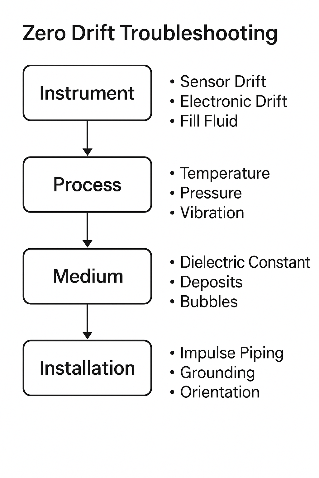
Zero drift appears as “wrong numbers” on the display, but its essence is the baseline deviation of the measurement chain. The causes can be categorized into four major groups:
2.1 Instrument-Intrinsic Factors
Sensor aging: Diaphragms in DP level transmitters, electrodes in capacitance meters, and strain gauges may degrade under long-term high temperature and pressure.
Electronic component drift: Operational amplifiers, resistors, and capacitors may change characteristics over time or temperature, leading to accumulated offset.
Filling liquid and sealing: Remote seal DP transmitters may suffer from evaporation or leakage of fill fluid in capillaries, causing continuous drift.
2.2 Environmental & Process Conditions
Thermal stress: Expansion of capillaries or sensing elements with temperature rise shifts the zero point.
Mechanical stress & vibration: Tank wall stress or long-term vibration loosens mounting structures.
Electromagnetic interference: Frequency converters, motors, and high-frequency signals disturb the baseline signal.
2.3 Medium & Process Characteristics
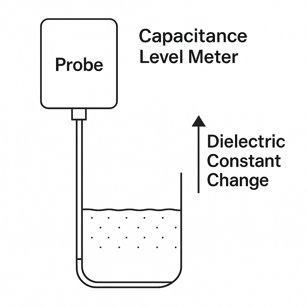
Dielectric constant changes: Capacitance-type meters are highly dependent on the dielectric constant; temperature, concentration, or composition variations shift zero.
Deposits and clogging: Scaling in impulse lines or flanges causes uneven pressure.
Bubbles & vapor: Gas bubbles on membranes or radar antennas result in false levels.
2.4 Installation & Maintenance Issues
Improper installation: Insufficient slope of impulse lines, poor grounding, or incorrect mounting angles.
Incorrect calibration: Not allowing for thermal stabilization; calibration environment differs from actual conditions.
Inadequate maintenance: Lack of periodic purging, loose shielded cables, or aging wiring.
3. Risks and Hidden Costs of Zero Drift
Process control deviation:
False high reading → premature pump shutdown.
False low reading → risk of dry running or cavitation.
Energy & capacity loss: Abnormal column levels reduce separation efficiency and increase energy use.
Safety hazards: Distorted alarms may lead to overflow or dry heating accidents.
Management & compliance risks: For oil and chemical tanks, inaccurate levels cause inventory errors or legal issues.
4. Case Studies
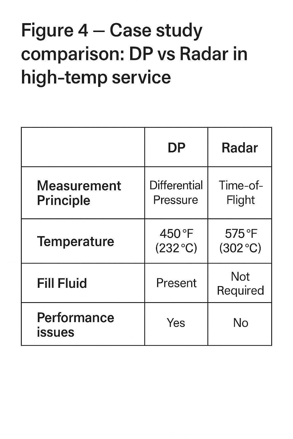
Refinery DP Level Transmitter Drift
In a refinery’s atmospheric tower, capillary fill fluid evaporated under summer heat, drifting zero by 15%. This misled operators and triggered incorrect operations.
Lesson: In high-temperature service, prefer remote-seal radar level transmitters to reduce reliance on fill fluid.
Food Plant Capacitance Level Meter Drift
After CIP cleaning, dielectric changes due to residual cleaning solution shifted the zero baseline.
Lesson: For frequent cleaning processes, use guided-wave radar meters that are independent of dielectric constant.
5. Preventive Measures and Corrective Actions
5.1 Engineering Selection
High-temperature/high-pressure: Remote DP or radar level meters.
Scaling media: Non-contact radar or ultrasonic meters.
5.2 Installation Optimization
Ensure impulse lines are free from gas blockage and deposits.
Maintain proper grounding to avoid EMI.
5.3 Operational Management
Periodically re-check zero (empty tank or reference level).
Apply temperature compensation and software filtering.
5.4 Intelligent Maintenance
Use online diagnostics to detect abnormal zero drift.
Build historical databases to analyze long-term drift trends and predict anomalies.
6. From Passive Calibration to Active Diagnostics
With Industry 4.0 and intelligent manufacturing, level measurement is evolving:
Self-diagnosis & self-calibration: Advanced transmitters integrate temperature compensation and adaptive learning algorithms.
Digital twins & big data: Historical drift data supports predictive models.
Maintenance-free design: Non-contact FMCW radar and fiber-optic level meters reduce mechanical stress and deposits.
7. Conclusion
Zero drift in level meters is not a “minor issue.” It is a lifecycle-wide challenge involving design, selection, installation, operation, and maintenance.
For engineers: learn to diagnose and correct quickly.
For management: consider drift as part of asset lifecycle costs.
In the future, with intelligent diagnostics and data analytics, zero drift will become measurable, predictable, and manageable, rather than a problem solved only by experience.