Process instrumentation in the chemical industry relies heavily on signal transmission and power supply methods. The wiring configuration of transmitters and sensors—whether two-wire, three-wire, or four-wire—directly affects installation complexity, cost, measurement accuracy, and reliability.
This article explains the principles, advantages, limitations, and typical applications of each wiring system, providing a comparative overview for engineers and procurement professionals.
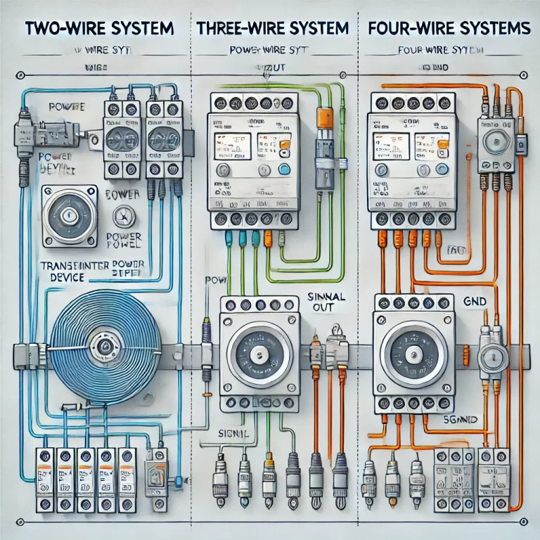
2. Two-Wire System
Principle
In a two-wire system, the transmitter is powered through the same two conductors that carry the measurement signal, typically in a 4–20 mA current loop.
Features
Power + Signal in same loop → reduces cabling.
4–20 mA signal inherently immune to voltage drops and noise over long distances.
Widely used in pressure transmitters, temperature transmitters, flowmeters.
Advantages
Simple wiring and reduced installation cost.
High noise immunity.
Compatible with intrinsic safety barriers for hazardous areas.
Limitations
Power budget is limited by loop resistance (load).
Restricted in high-power or multi-output applications.
3. Three-Wire System
Principle
In a three-wire system, two wires provide power supply (positive and negative), while the third wire carries the output signal referenced to the negative.
Features
Typical for voltage output transmitters (e.g., 0–10 V).
Common in RTD (Pt100) three-wire circuits, where the third wire compensates for lead resistance.
Advantages
Better accuracy for resistive sensors (lead wire compensation).
Suitable for medium power sensors.
Limitations
Requires a common ground; potential risk of ground loops.
Slightly higher wiring complexity and cost than two-wire.
4. Four-Wire System
Principle
In a four-wire system, the sensor/transmitter has two wires for dedicated power supply and two separate wires for signal output.
Features
Power supply and signal path are fully isolated.
Typical in digital transmitters, analyzers, high-power flowmeters.
Advantages
Supports higher power consumption devices.
Reduces measurement errors from voltage drops.
Enhanced isolation improves measurement accuracy.
Limitations
Higher cabling and installation cost.
Requires additional planning for routing and termination.
5. Comparative Overview
Table 1 — Comparison of Two-Wire, Three-Wire, and Four-Wire Systems
The choice between two-wire, three-wire, and four-wire systems is not universal; it depends on the application, accuracy requirements, power budget, and safety considerations. Understanding these differences helps engineers optimize cost, reliability, and performance in chemical process plants.