Level Measurement Principle and Troubleshooting of Water Seal Tank - Just Measure it

Level Measurement Principle and Troubleshooting of Water Seal Tank

1. Operating Conditions

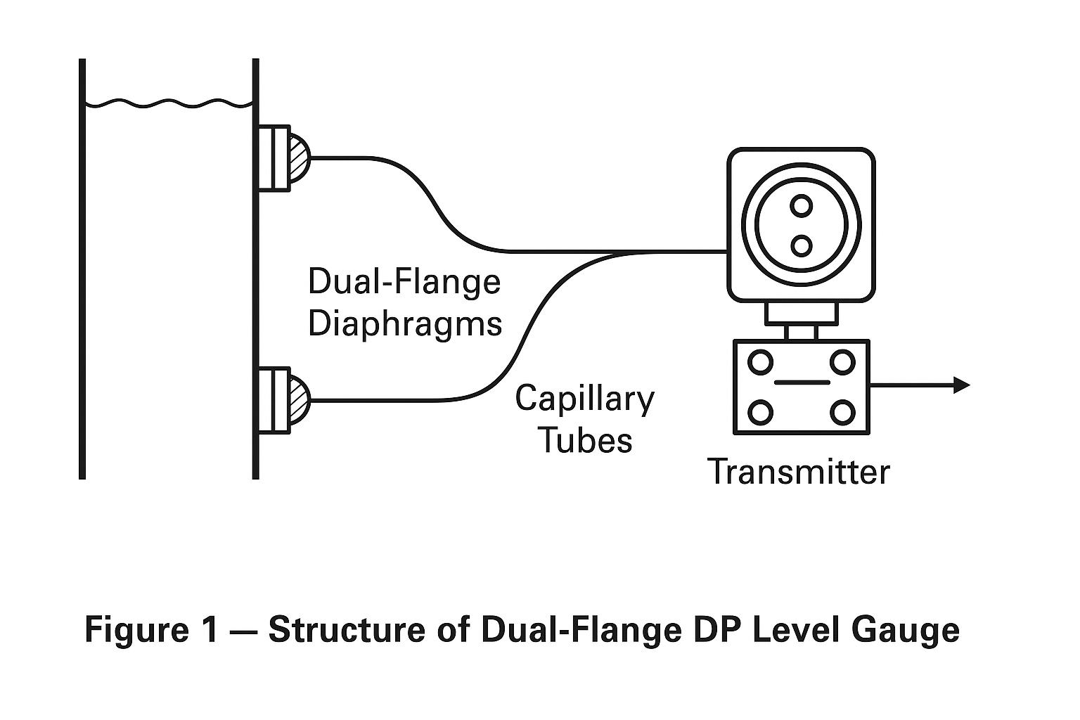
The water seal tank level gauge is installed in the flare system (Unit 80). It is a critical instrument for monitoring the liquid level in the water seal tank, ensuring safe operation of the flare tail gas treatment system.

  • High level condition: When the level exceeds the setpoint, the gauge generates an alarm, triggering the closure of the inlet shut-off valve to prevent further inflow.

  • Low level condition: When the level falls below the limit, the inlet valve opens automatically to replenish water and maintain system safety.

2. Safety Precautions Before Maintenance

  1. Obtain a maintenance work permit.

  2. Wear personal protective equipment (safety shoes, pants, helmet, gloves).

  3. Prepare necessary tools (adjustable wrench, spanner, multimeter, screwdriver, HART 475 communicator).

  4. At least two people must be present—one monitoring, one operating—with radio communication.

  5. Carry a portable gas detector, ensure no gas leakage, identify upwind direction, and plan emergency escape route.

  6. Avoid contact with corrosive process media during disassembly.

3. Structure of the Differential Pressure (DP) Type Level Gauge

  1. Dual-flange diaphragms: Mounted at the top and bottom of the tank, directly in contact with the process medium.

  2. Capillary tubes: Filled with silicone oil, transmitting pressure signals to the transmitter.

  3. Differential pressure transmitter: Converts pressure difference into electrical output (4–20 mA).

  4. Mounting bracket: Provides stability and prevents vibration-induced movement.

4. Working Principle

The gauge operates based on the linear relationship between hydrostatic pressure and liquid level height.

  • Rising liquid → diaphragm deformation → pressure transmitted via silicone oil → transmitter converts signal to 4–20 mA output.

  • Output varies proportionally with the liquid level difference.

5. Installation Guidelines

  1. Avoid welding current through the transmitter and prevent weld slag from damaging diaphragms.

  2. Install HP (high-pressure) and LP (low-pressure) flanges correctly; zero reference should be ≥50 mm above HP diaphragm center.

  3. Protect diaphragm surface from scratches; avoid downward placement.

  4. Bundle HP and LP capillaries together to minimize temperature effect; avoid twisting or crushing.

6. Wiring Requirements

  1. Keep cables away from strong electrical interference (large motors, transformers).

  2. Seal cable glands properly against dust and water ingress.

  3. Signal cables should not share conduit with power cables.

  4. For explosion-proof models, follow IEC/GB Ex-proof wiring codes strictly.

7. Maintenance and Inspection Guidelines

  • Inspection cycle: Typically once per plant operating cycle.

  • Perform purging at connection points (do not blow steam directly on diaphragm).

  • Disassemble flange if no drain is available for cleaning.

  • Check for corrosion, wear, deformation, and leakage.

8. Range and Zero Suppression (Elevation Calibration)

Calibration after installation using a HART communicator:

  • Zero suppression (P):
    P=Hρ0gP = H \cdot \rho_0 \cdot g

  • Span (ΔP):
    ΔP=Hρg\Delta P = H \cdot \rho \cdot g

  • Measurement range:
    Hρ0g  to  (HρgHρ0g)-H \cdot \rho_0 \cdot g \; \text{to} \; (H \cdot \rho \cdot g – H \cdot \rho_0 \cdot g)

Where:

  • H = measuring height (mm)

  • ρ = medium density (g/cm³)

  • ρ₀ = fill liquid density (g/cm³)

  • g = gravitational acceleration

9. Common Faults and Diagnosis

SymptomPossible CauseCorrective Action
No outputPower loss, loose wiringReconnect wiring, check power supply
Full-scale or zero outputDiaphragm or capillary damage, oil leakageReplace diaphragm/capillary or transmitter
Output driftVent plug leakage, valve partially closedTighten plugs, open valves
No change in outputPCB failure or both diaphragms damagedReplace circuit board or transmitter

10. Preventive Measures & Improvements

  1. Increase routine inspection frequency; monitor transmitter trend curves.

  2. Record operating cycles, schedule diaphragm cleaning to avoid fouling.

  3. Regularly check supply voltage (24 VDC).

  4. Protect outdoor transmitters against rain and humidity ingress.

Conclusion

The water seal tank DP-type level gauge ensures safe operation of the flare system by maintaining accurate level monitoring. Proper installation, wiring, periodic calibration, and preventive maintenance are essential to minimize failures and extend service life.

Share This Story, Choose Your Platform!

Contact Us

    Please prove you are human by selecting the truck.
    Translate »