1. Core Installation Principles
1.1 Flow Direction and Vertical Alignment
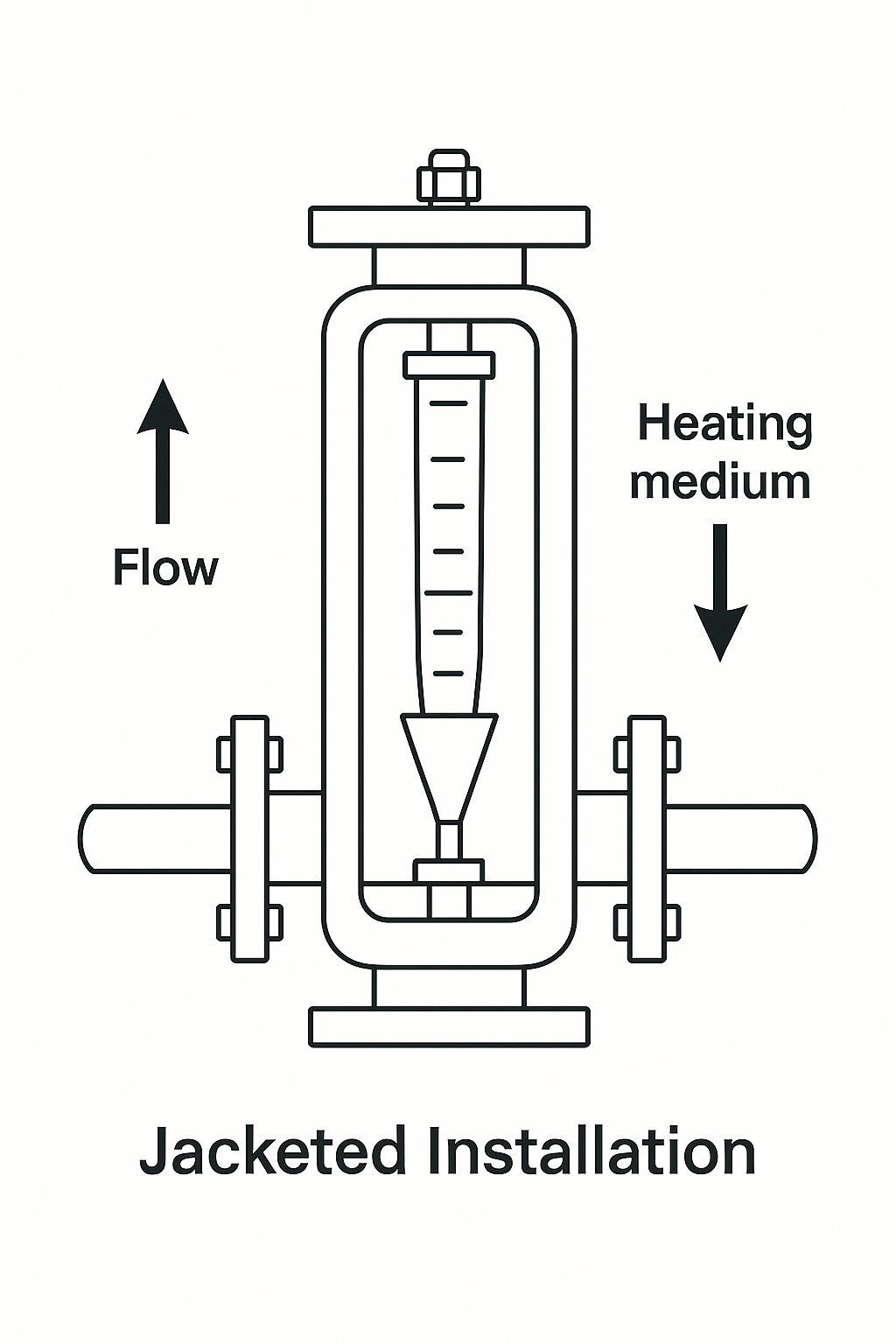
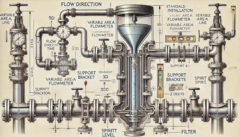
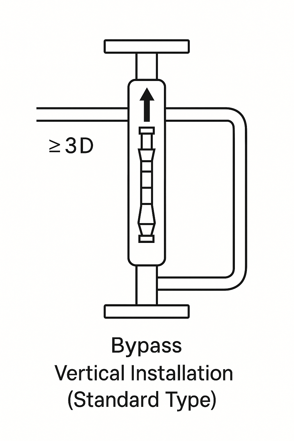
The rotameter must be installed vertically, with fluid flowing from bottom to top through the tapered tube.
The deviation from the vertical axis should be less than 2°.
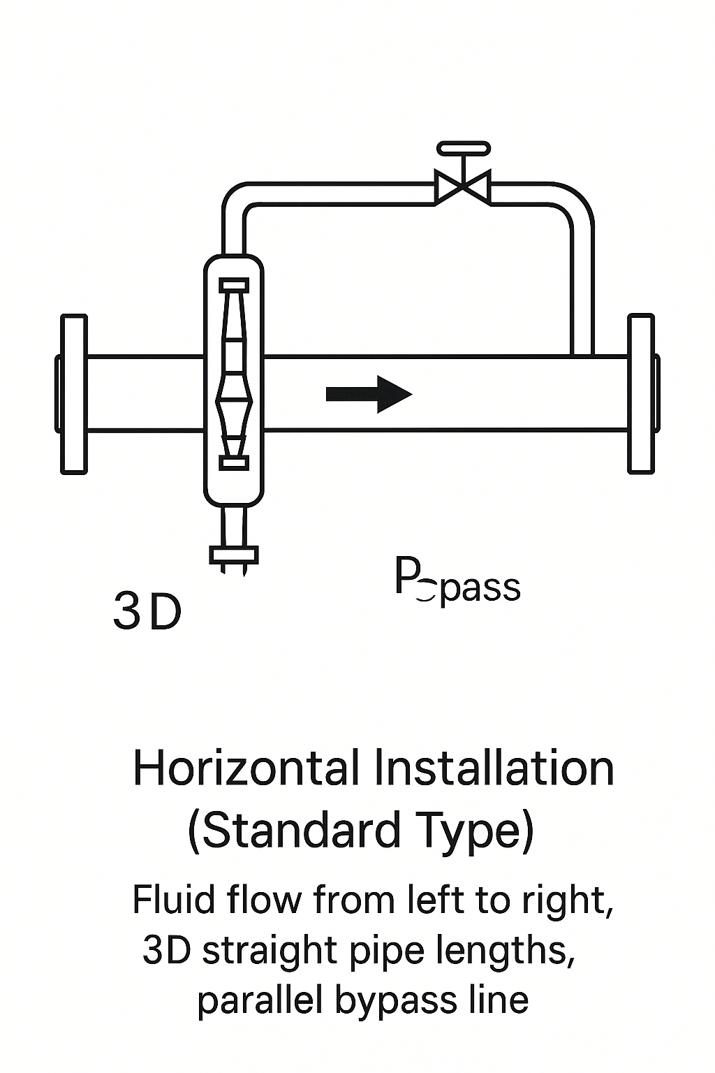
For special horizontally-installed models, ensure the measuring tube remains level, with full pipe conditions. Horizontal deviation should also be within 2°.
Use a plumb line or spirit level for calibration to prevent float jamming or inaccurate measurement.
1.2 Straight Pipe Requirements
Upstream: Minimum 5D straight pipe length (where D = pipe diameter).
Downstream: At least 3D or more than 250 mm.
If turbulence-inducing components (elbows, valves) exist upstream, increase straight pipe to 20D–25D.

2. Key Installation Steps & Precautions
(1) Pre-Installation Preparation
Pipe Cleaning: Flush to remove welding slag, iron filings, etc.
Use magnetic filters for ferromagnetic media;
Install standard filters if solid particles exist.
Parameter Verification: Confirm rated temperature and pressure.
For example, glass rotameters need protective covers when temperature > 70°C.
(2) Installation Process Control
Supports & Stress Relief:
Piping should be supported to prevent load on the meter.
For PTFE-lined meters, tighten flange bolts symmetrically.
Metal-tube meters should have support near flanges to minimize vibration.
Bypass Design:
A parallel bypass line with valves is recommended.
Operate in mainline mode; switch to bypass for maintenance.
Valve positions should allow easy operation.
(3) Connection & Sealing
Flange Matching:
Flanges must be coaxial and parallel.
Bolts should be evenly torqued to avoid deformation.
Electrical Connection:
For remote signal models, check grounding of shielded cable.
Explosion-proof types must ensure junction box sealing meets standards.
3. Special Operating Conditions
3.1 High Temperature & Vibration
Glass rotameters over 70°C require protective covers.
Secure upstream/downstream piping to prevent thermal expansion cracks.
Use flexible joints or dampers if installed near pumps or compressors.
3.2 Liquid vs. Gas Measurement
Liquids:
Ensure full pipe conditions; install air release valve at high point.
Gases:
Avoid condensate buildup in horizontal lines;
For vertical, maintain bottom-to-top flow.
4. Commissioning & Maintenance
Slow Start-Up:
Gradually open valves; avoid float damage due to sudden flow.
Recommended: open bypass first, then switch to mainline.
Calibration & Cleaning:
Regularly check float mobility and clean if needed.
For electronic types, verify 4-20 mA output accuracy.
Long-Term Shutdown:
Drain media to avoid corrosion/crystallization.
Secure the float during transport.
5. Typical Installation Diagrams (To Be Added)
Standard Vertical Installation
Fluid flows bottom to top
Includes 5D/3D straight pipe and parallel bypass
Horizontal Installation (Special Design Only)
Ensure full pipe
Drain valve recommended at low point
Jacketed Flowmeter Installation
Thermal jacket for heating/cooling
Flanges tightened symmetrically to avoid jacket deformation
6. Applicable Standards & References
China Standard: GB50093-2013 “Specifications for Installation & Acceptance of Instrumentation Engineering”
International Standard: VDI/VDE 3513 for scale correction based on viscosity
Manufacturer Manual: Refer to rotameter datasheet (e.g., installation dimensions table below)
Nominal Size (DN) | Flange Outer Diameter (D) | Bolt Hole (n×d) | Installation Length (L) |
---|---|---|---|
DN15 | 95 mm | 4×14 | 80 mm |
DN50 | 165 mm | 4×18 | 104 mm |
DN100 | 220 mm | 8×18 | 130 mm |
7. Common Errors & Prevention
Error | Issue | Prevention |
Reverse Installation | Float stuck or unstable | Confirm arrow direction; bottom-to-top flow |
Inadequate Straight Pipe | Measurement fluctuation | 5D upstream + 3D downstream; install flow straightener if needed |
No Bypass Line | Shutdown required for maintenance | Install cutoff valves and bypass (3-valve group) |
By following these technical guidelines, rotameters can operate stably and maintain measurement error within ±1.5% FS (or ±1% FS for high-precision types). Always consult the model-specific manual and involve qualified personnel during setup.