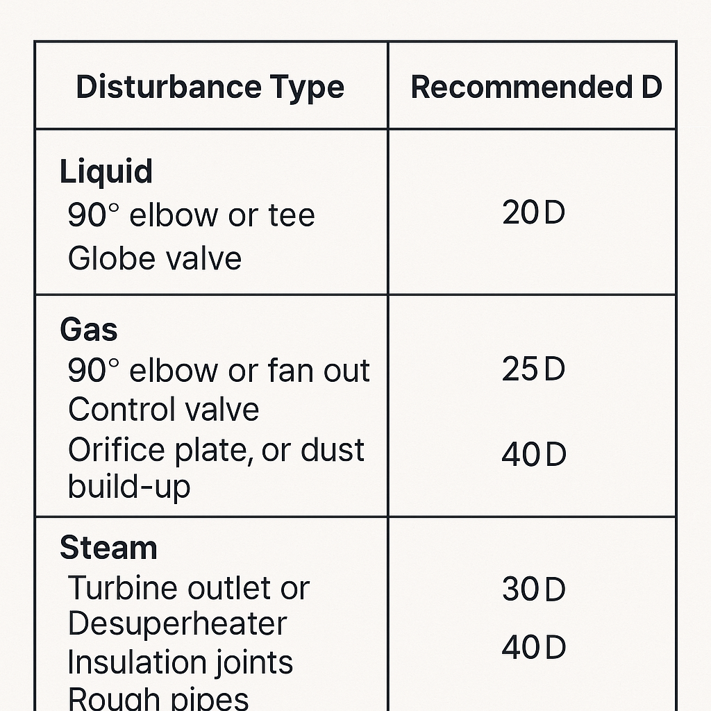
For dusty gas or slurry‑like liquids, extend upstream to ≥ 40D–50D and downstream ≥ 10D–30D as needed.
Small bore (D < 100 mm): add ~50% to the numbers above.
If space is tight: consider paired, symmetric elbows to partially cancel swirl, then keep ≥ 10D (single‑phase only).
Field tip: old, rough pipe or poor liner joints behave like extra disturbances—treat as +10D equivalent.
2) Cross‑Section Positioning (horizontal runs)
Principle: avoid phase segregation regions so all sensing ports see a representative bulk phase.
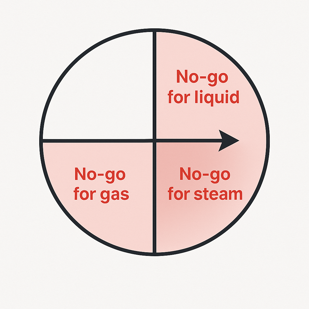
2.1 Liquids
Place the probe within 0°–45° below the horizontal centerline (i.e., just below midline).
Avoid top (gas pockets) and bottom (sediment) zones.
2.2 Gases
Place the probe within 0°–45° above the horizontal centerline.
Avoid bottom zone where condensate/dust accumulates.
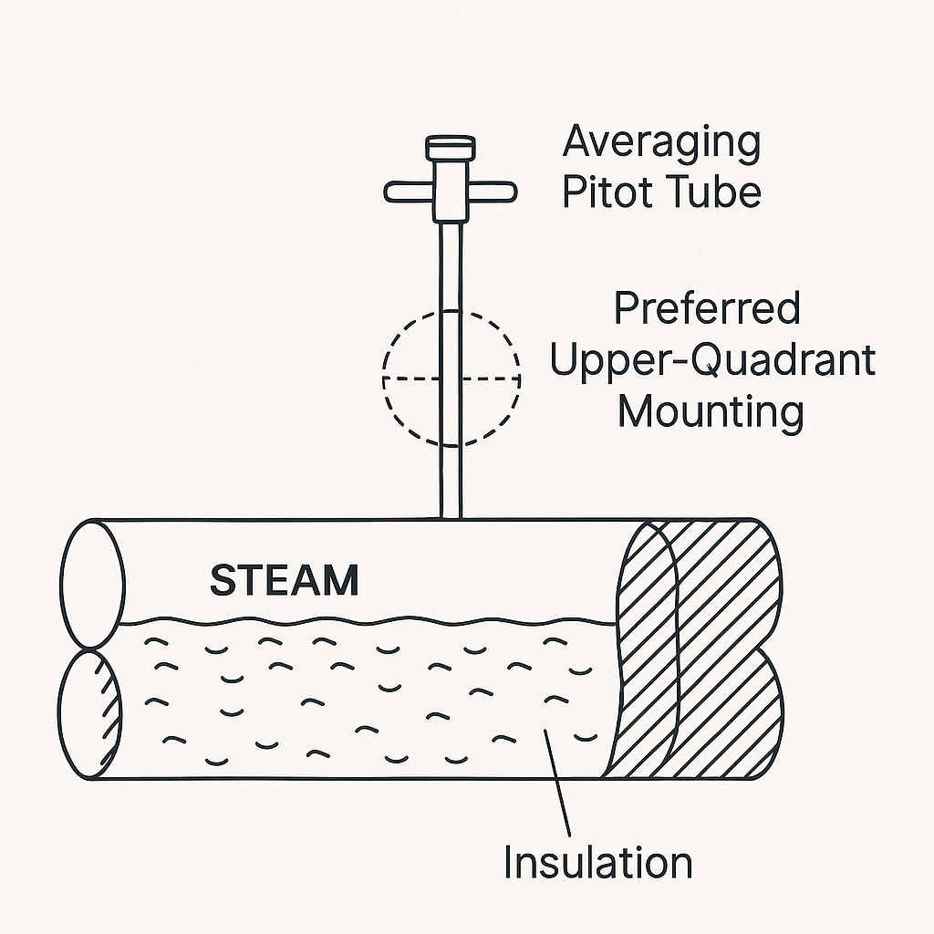
2.3 Steam (esp. wet steam)
Treat as two‑phase. Do not mount in the bottom quadrant (90°–180°) where liquid film/droplets pass; this causes DP bias and noise.
Prefer the upper quadrant; use insulation and high‑temp isolation practices.
Orientation check: verify insertion angle with a laser alignment tool; ±2° max error. High/low ports must face true flow direction.
3) Impulse/Take‑off Design & Anti‑Interference
Use short, direct, equal‑length runs for high/low lines. Minimize vertical loops.
For dirty liquids, specify anti‑plugging ports (chamfered or conical) and purge fittings; schedule periodic inert‑gas purges.
Steam: avoid U‑loops and condensate pots that trap liquid and drift the zero. Keep lines sloped back to the process; provide heat shielding and weather hoods outdoors.
Consider capillary with fill fluid for long runs or high vibration.
4) Materials & Environment
Default 316L for wetted parts in mildly corrosive media; upgrade as required.
Outdoor installs: fit rain/sun hood, maintain insulation integrity, protect capillaries.
5) Commissioning Checklist (one‑page)
Tag & range match P&ID; density/pressure/temperature data confirmed.
Upstream/Downstream straight runs measured and recorded.
Insertion depth and port orientation verified (±2°).
Impulse lines: equal length, slope toward process, no low pockets.
Purge/vents tested; zero stability check at no‑flow.
Damping/filter set to suppress high‑frequency noise; log baseline DP at 3–5 stable loads.
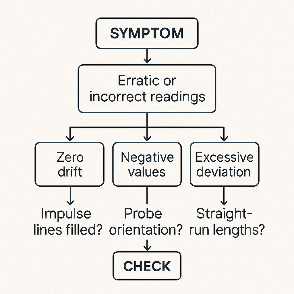
6) Troubleshooting (symptom → likely cause → action)