1) Define the Duty (Process Requirements)
Maintain temperature (Tₘ): e.g., anti-freeze (>0 °C) or process hold (50–100 °C).
Max exposure temperature (Tₑₓₚ): abnormal heat, upset, or external sources. Select jacket & cable class with T rating ≥ Tₑₓₚ.
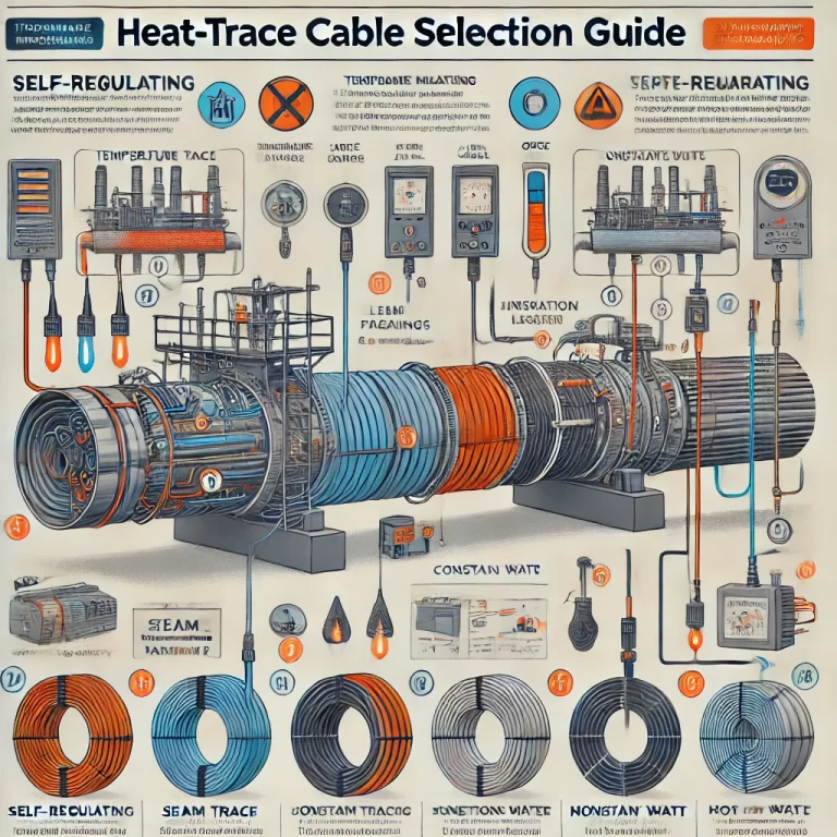
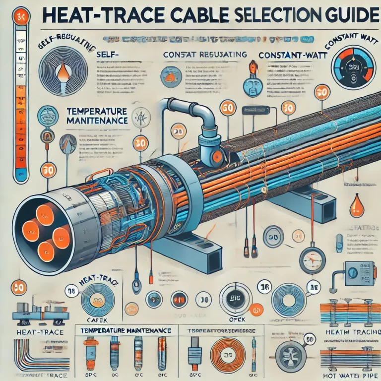
Recommended cable type by duty
Self-regulating (SR): maintain ≤ ~130 °C; auto-throttles output, safer on overlaps.
Constant-watt (CW): single-/parallel-conductor; maintain ≤ ~150 °C (single-phase), higher on 3-phase; must use controller.

2) Size the Power (Compensate Heat Loss)
Estimate heat loss (q, W/m): function of pipe OD, insulation thickness/λ, ambient Tmin, wind, emissivity.
Match cable output: choose W/m @ Tₘ (e.g., 10/20/30/40 W/m). Use multiple runs or higher rating if q > one run’s output.
Length limits: CW has strict max circuit length (voltage/power dependent); SR is more forgiving but consider voltage drop. Segment long runs.
3) Check the Environment
Chemical/corrosion: select FEP/fluoropolymer or reinforced polyolefin jackets; protect braid/core from attack.
Moisture/ingress: target IP68 or better if buried/submerged; use sealed power/termination kits.
Hazardous area: require appropriate Ex certification (e.g., Ex d IIC T4 or per local code) and correct temperature class.
Mechanical abuse: choose armored or heavy-duty jacket; verify minimum bend radius (typ. ≥5×OD for SR, ≥10×OD for CW).
4) Match the Hardware (Pipe/Equipment)
Geometry: straights, bends, valves, flanges, tanks → affects layout (straight, helical wrap, multi-run).
Material: metal pipes conduct well; plastics may need higher W/m or closer wrap.
Specials: add extra length around valves/flanges (≈1.5–2× circumference). Allow slack for expansion joints (~1.2× expansion).
5) Power & Controls
Supply: 220 VAC common; some use 380 VAC. Match cable rating.
Control level: simple on/off thermostat vs. PID/remote monitoring with RTD/TC sensors and alarms.
Protection: RCD/GFCI ≤30 mA; proper circuit breakers per inrush/steady current of SR/CW.

6) Installation Rules (Do/Don’t)
Do
Fix with high-temp tape (e.g., aluminum) at 0.5–0.8 m spacing; keep runs evenly spaced for helical wraps.
Use certified power/tee/end-seal kits; bond braid to earth; verify earth ≤4 Ω.
Perform IR test before & after install, and a brief energized test before insulation (10–15 min).
Don’tDon’t over-bend, cross, or tightly overlap CW runs (hot spots).
Don’t drag on rough ground or across sharp edges; use pads at welds/angles.
Don’t bury junction/termination boxes under insulation; keep sensors accessible.
7) Commissioning Checklist
Cable model, W/m @ Tₘ, voltage, approvals match datasheet.
Circuit length within manufacturer max; voltage drop checked.
IR ≥ manufacturer minimum to ground and between conductors.
Controller setpoints & high-temp cutout verified; alarms tested.
Insulation thickness/material installed; weather jacketing sealed.

8) Alternative Heat-Maintenance Methods (Quick Comparison)
| Method | Heat Source | Capex | Opex | Control Accuracy | Heat Transfer | Notes |
|---|---|---|---|---|---|---|
| Steam tracing | Boiler steam | Mid | Mid-High | Low | Low | Robust, high output; needs steam plant/piping. |
| Hot-water tracing | Plant hot water | Mid | High | Mid | Low | Can reuse low-grade heat; higher line losses, lower control. |
| Electric heat-trace | Electricity | High | Low | High | High | Precise, modular; needs proper design/controls. |
| Self-heating (“self-trace”) | Process fluid | Low | Mid | Mid | Mid | Only if process allows; limited range. |

9) Example Spec Lines (Copy/Paste)
Cable: Self-regulating, 230 VAC, 20 W/m @ 10 °C, FEP over-jacket, tinned copper braid, T-rating ≥ Tₑₓₚ.
Circuit: Max run length per mfr; supply MCB + 30 mA RCD; junction/tee/end-seal kits per system vendor.
Controls: Wall-mount temperature controller with Pt100 sensor, high-temp cutoff, local alarm relay, Modbus/RS-485 (if required).
Install: Helical wrap on DN50, 45° valve add-length 1.5× circumference, tape at 0.6 m intervals, sensor placed on shaded, metal-to-metal contact point under insulation.
Test & Handover: IR and load tests logged; as-built route sketch; spare kit list.
