0. Abstract
This document summarizes core selection principles and field-proven troubleshooting methods for six mainstream flowmeter types: Orifice (standard DP), Averaging Pitot Tube, Flow Nozzle, Vortex, Ultrasonic, and Variable Area (Rotameter). It is intended for plant design reviews, commissioning, and maintenance.

1. Selection Principles (Five Key Factors)
1) Instrument performance
Range setting: Upper range ≈ 1.2–1.3 × maximum expected flow; keep normal operating point within 30–70% of span.
Accuracy & stability: Consider accuracy class, repeatability, long-term drift, and response time.
Pressure-loss sensitivity: Throttling devices (orifice/nozzle) create permanent pressure loss; in energy-sensitive applications prefer low-ΔP options (nozzle/Venturi/ultrasonic/rotameter).
2) Fluid properties
Conductivity, viscosity, density/compressibility, solids/entrained gas, crystallization tendency.
Pressure/temperature window: instrument pressure rating ≥ 1.25 × operating; select wetted materials (seals/liners) for chemical compatibility.
3) Installation conditions
Straight-run & full pipe: Observe upstream/downstream run requirements by meter type; most liquid services require a full pipe.
Impulse/tapping & space: Route impulse lines sensibly; provide accessible isolation, vent, and drain points.
4) Environment
Safety: Use Ex-rated devices in hazardous areas; remote mounting/rigid supports for high vibration; corrosion-proofing for humid/salt-mist environments.
EMC: Shielding and single-point grounding in strong EMI fields.
5) Economics
Evaluate CAPEX + OPEX + energy loss (ΔP) + downtime risk; standardize on widely supported models that are easy to maintain.
Standards (for reference): HG/T 20507-2014 (instrument selection), SH/T 3104-2013 (petrochemical instrument installation). Always follow the latest manufacturer instructions.
2. Type-by-Type Guidance
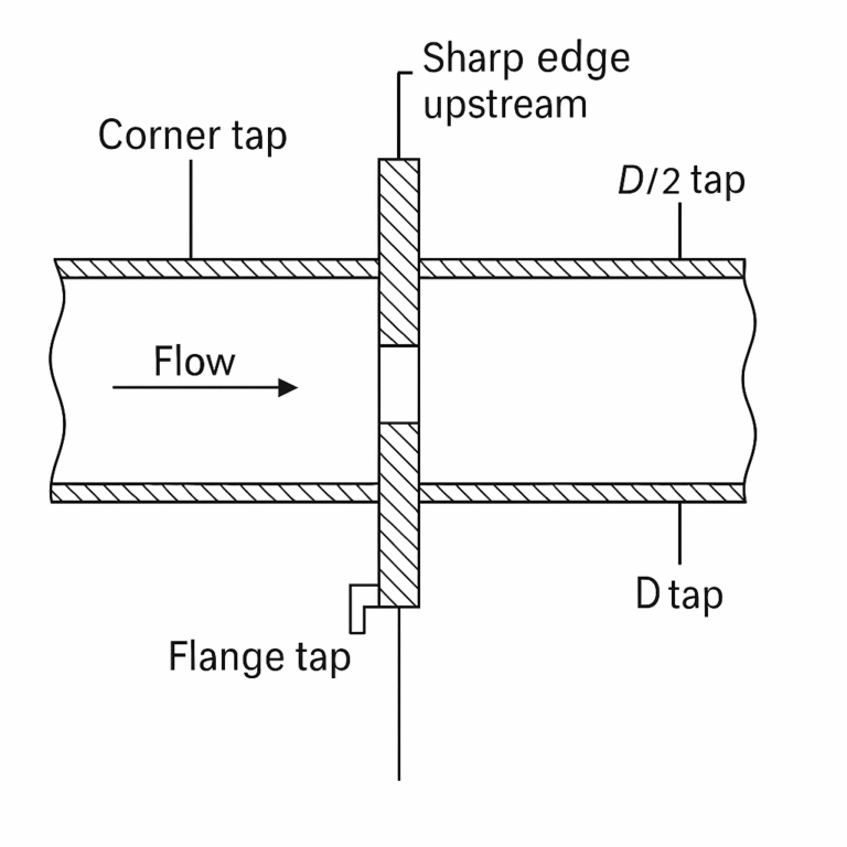
2.1 Orifice Plate (Standard Throttling Device)
Application features
Simple, universal, suitable for high temperature/pressure; accuracy depends on straight-run and machining quality; higher permanent ΔP than nozzle/Venturi.
Typical faults & remedies
Impulse leakage/blockage: Replace gaskets/ferrules to matching rating; clear lines; maintain vents/drains; keep impulse-line slope ≥ 1:12, bend radius ≥ 5 × OD.
Wrong orientation/perpendicularity (reversed/offset/burrs): Sharp edge faces upstream; plate face perpendicular to pipe axis; verify β-ratio and concentricity; standard chamfer/edge finish.
Erratic indication: Re-zero/re-range DP transmitter; ensure only one square-root is applied (transmitter or DCS); add damping/digital filtering; remove flow pulsation and pipe vibration; verify shield/grounding.
Edge wear/fouling → coefficient shift: Periodic inspection/cleaning; for dirty service consider segmental (eccentric) plate or purge ring; replace primary element as needed.
Excess ΔP: Optimize β; shift to nozzle/Venturi; or increase line size to reduce velocity.
Installation/sizing notes
Materials ≥ 304SS typical; prefer Re > 5,000 for standard sharp-edged concentric plates.
Where ΔP is constrained, prefer nozzle/Venturi; meet straight-run or add a flow conditioner.
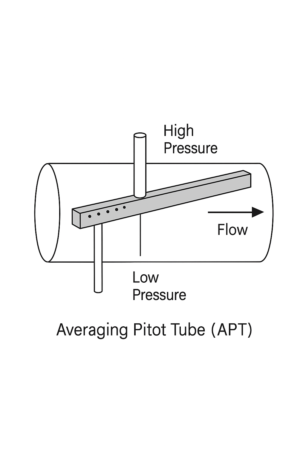
2.2 Averaging Pitot Tube (APT)
Application features
Low pressure loss, compact; good for large diameters and retrofits with limited space; sensitive to straight-run and orientation.
Typical faults & remedies
No output/zero: Confirm arrow orientation matches flow; ensure full pipe; check sensing holes are not covered by fouling.
Strong fluctuation: Add straight-run or flow conditioner; purge gas/liquid pockets from impulse lines; increase transmitter damping/averaging; stiffen supports to reduce vibration.
Indication error (leak/zero/span): Leak-check and reseal; re-zero; align transmitter/DCS ranges; ensure single square-root.
Wiring/EMC issues: Tighten terminals; proper shielding and single-point ground; route away from high-interference cable bundles.
Installation/sizing notes
Follow recommended clocking position for horizontal runs (per industry practice); observe upstream/downstream runs per manufacturer; avoid pulsating/non-full-pipe service when possible.
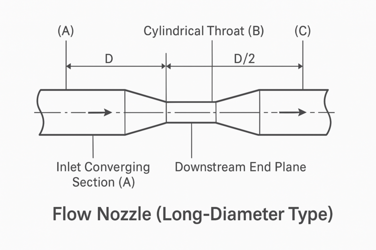
2.3 Flow Nozzle
Application features
Lower permanent ΔP than orifice; better anti-fouling and erosion resistance; suitable where ΔP limits and medium-to-high velocities apply.
Typical faults & remedies
No display/no ΔP: Verify power/fuse/signal integrity; check pressure taps are clear; confirm transmitter status.
High/low or inaccurate readings: Re-zero/re-range; clear/repair impulse lines; verify density, temperature/pressure compensation, and algorithm configuration.
Large fluctuation (bubbles/solids/vibration/EMI): Degas/filter upstream; stiffen piping; improve shielding/grounding; add damping/time averaging.
Installation/sizing notes
Observe straight-run and pressure-tap positions per standards and vendor guidance; a good fit for ΔP-sensitive and abrasive services.
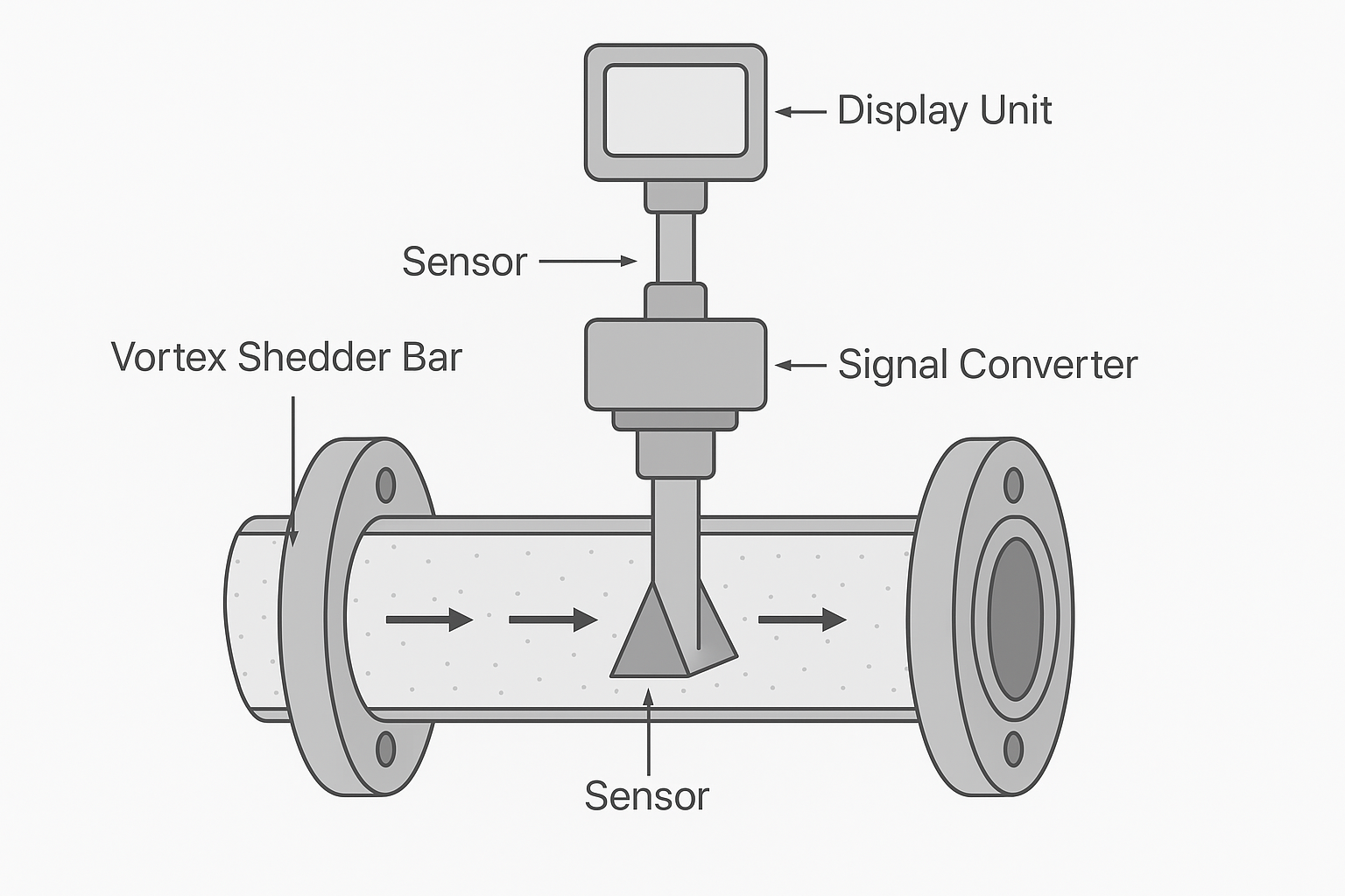
2.4 Vortex Shedding
Application features
Works for gases, steam, liquids; simple construction, moderate turndown; sensitive to straight-run, vibration, and two-phase conditions.
Typical faults & remedies
No reading/over-aggressive low-flow cut: Increase velocity or select smaller bore; reduce low-flow cutoff; ensure Re & Strouhal regime is met.
Fluctuation/jumps (pipe vibration/resonance/pulsation): Upstream ≥ 15D, downstream ≥ 5D (use 20–30D after valves/elbows or add a conditioner); add rigid supports; enable filtering/averaging.
Bias due to medium state change/wet steam: Use temp/pressure compensation models; maintain dryness and steady conditions; for variable steam load, prefer integrated compensation type.
Probe fouling/blockage: Periodic cleaning; upstream filtration; add purge ports if needed.
Installation/sizing notes
Avoid close-coupled reducers/expanders, tees, valves; use cautiously on strong pulsation or two-phase flows.
2.5 Ultrasonic (Transit-Time dominant)
Application features
Clamp-on/insertion/spool-piece; zero pressure loss, virtually no pressure limit; ideal for retrofits. Sensitive to full pipe, bubbles/solids, and acoustic parameters.
Typical faults & remedies
No signal/low SNR: Verify OD, wall thickness, material, liner, and sound velocity; select appropriate V/Z/W path; avoid weld seams; refresh coupling gel.
Unstable/biased readings (not full/bubbles/solids): Choose a full-pipe location or vertical up-flow; add back-pressure to prevent cavitation; degas/filter; enable multi-averaging and stability criteria.
Parameter errors: Correct velocity model, temperature, attenuation compensation; for spool-piece types, perform zero/field calibration.
EMC/grounding: Single-point ground; proper shield termination; route away from VFD cables.
Installation/sizing notes
Typical straight-run: upstream ≥ 10D, downstream ≥ 5D (per vendor); clamp-on types are sensitive to wall scaling/coatings.
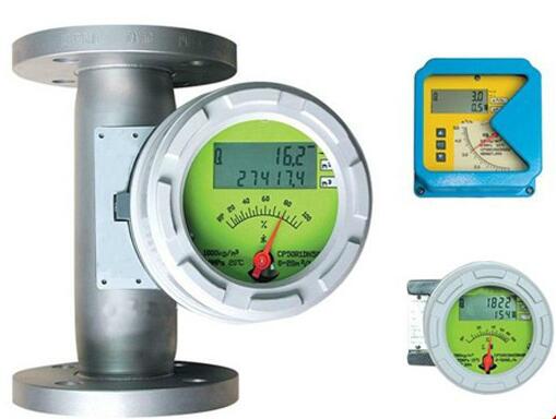
2.6 Variable Area (Rotameter)
Application features
Variable-area with metal- or glass-tube; simple, direct-reading, small ΔP; sensitive to mounting attitude; density changes affect indication.
Typical faults & remedies
Float sticking/creeping: Clean internals or add filtration; avoid ferromagnetic particles (for magnetic-coupled types); periodic recalibration.
Wrong mounting (needs vertical up-flow): Ensure verticality ≤ 2°; flow bottom-to-top; eliminate bypass leakage.
Two-phase/flash leading to anomalies: Add back-pressure valve to prevent flashing/cavitation (liquids); stabilize gas P/T; reduce flow pulsations.
Indication bias (range/density): Re-scale to operating density or use compensated types; keep normal flow at 30–70% of scale.
Remote signal failure: Check reed/Hall sensor and magnetic gap; verify 24 VDC supply and shielding/ground; reset alarm points.
Installation/sizing notes
Glass-tube types: ensure guarding and area classification; avoid strong vibration or add damping mounts.
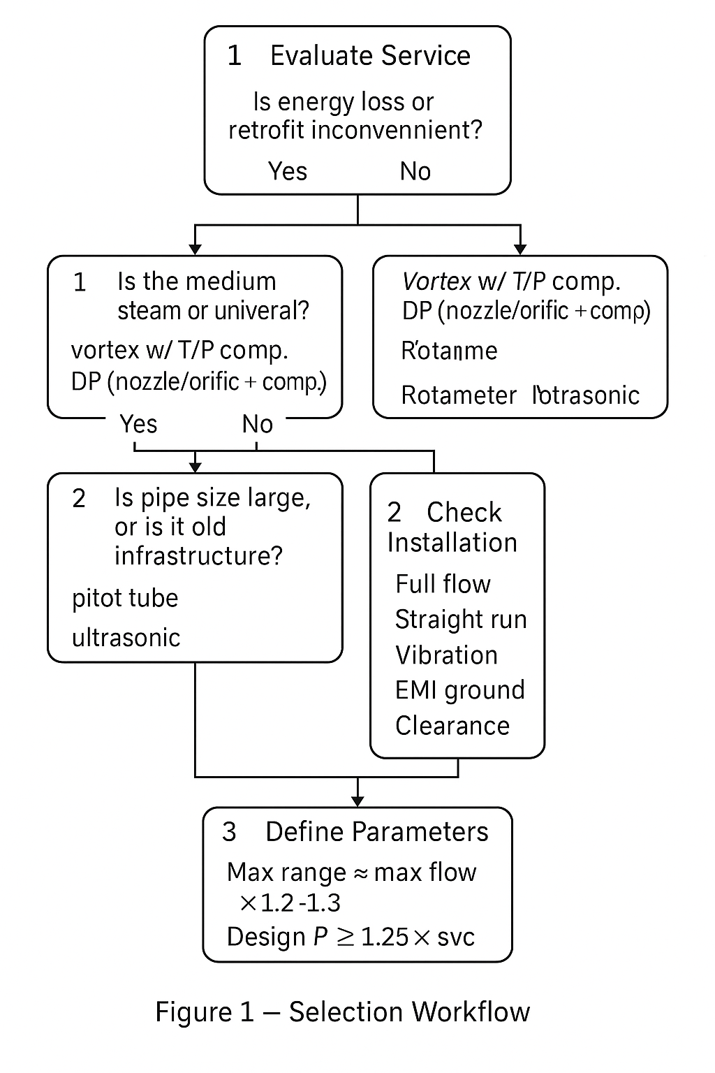
3. Field Implementation — Three-Step Selection
Start with service conditions
Strict ΔP / difficult retrofit: prefer ultrasonic (clamp/insertion) or nozzle/Venturi.
Steam & general utilities: vortex with temperature/pressure compensation, or DP (nozzle/orifice + compensation).
Large diameter/legacy stations: APT or ultrasonic.
Direct-read/low cost: rotameter (mind mounting and density effects).
Validate installation feasibility
Check full pipe, straight-run, vibration, EMC, grounding, and maintenance access one by one.
Fix data sheet parameters
Range upper limit ≈ max flow × 1.2–1.3; design pressure ≥ 1.25 × operating; lock in fluid properties and compensation method on the data sheet.
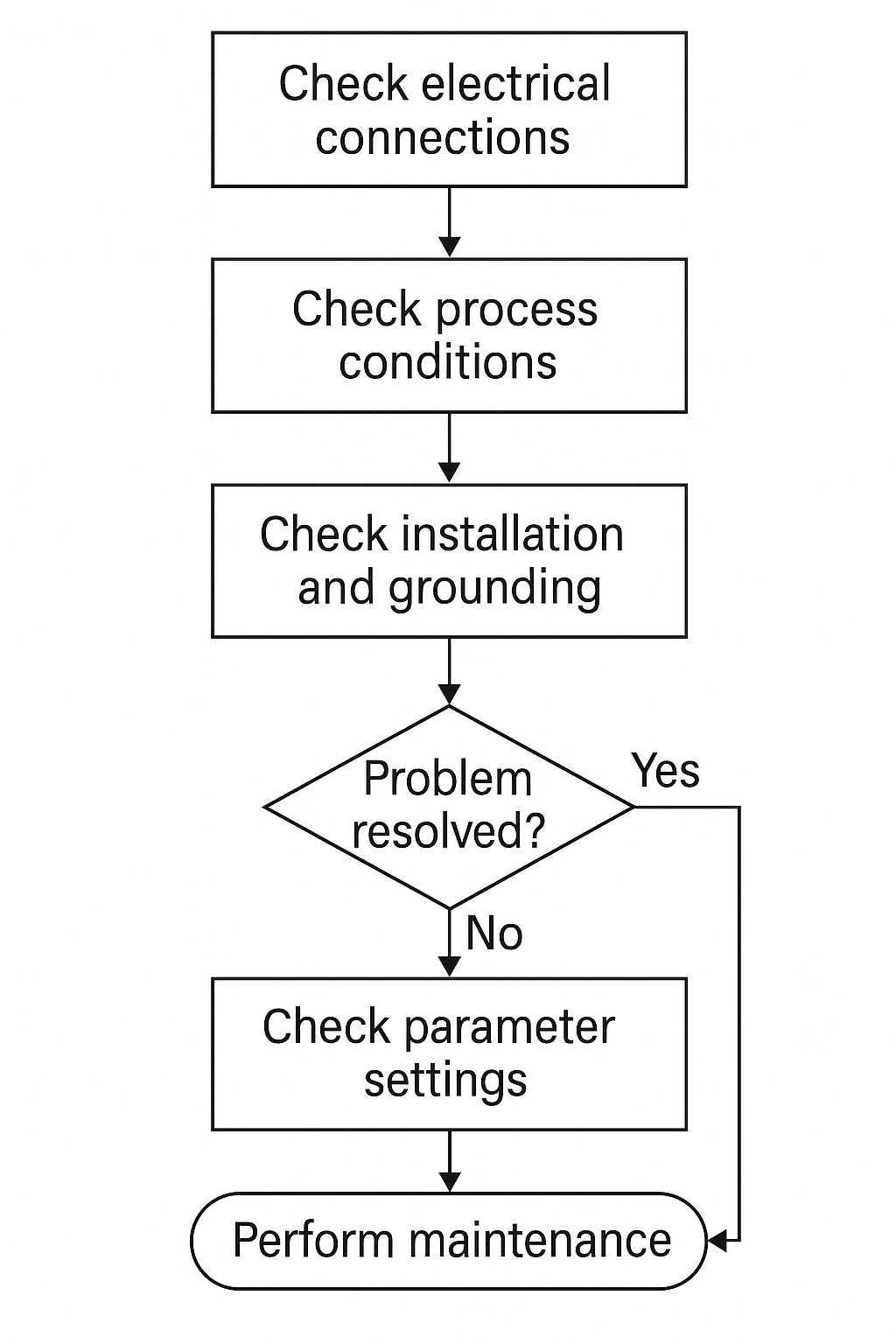
4. Quick Troubleshooting Checklist
Electrical first: power, fuses, terminals, grounding, shielding.
Then process: full pipe, bubbles/solids, pulsation, P/T deviations.
Installation: flow direction, straight-run, impulse routing, sensor tightness/orientation.
Parameters: zero/span/square-root, density & sound velocity, compensation terms, filtering/damping.
Maintenance: cleaning & inspection, venting/draining, periodic calibration & record keeping.
5. Common Pitfalls
Oversized range → poor sensitivity, amplified error. Size around the normal operating region.
Ignoring ΔP cost: throttling devices incur long-term energy penalties—quantify at design stage.
Insufficient straight-run: top field error source; if unavoidable, use conditioners or re-route.
Grounding/EMC negligence: drift and noise; enforce single-point grounding and proper shielding.
Forcing two-phase service: most meters are not two-phase capable; consider separation or stabilization upstream.
6. Tables
Table 1 — At-a-Glance Selection Matrix
| Meter Type | Typical Media | Accuracy (typ.) | Turndown | ΔP/Energy | Install Sensitivity | Notes |
|---|---|---|---|---|---|---|
| Orifice | Gas/Liquid/Steam | Medium | 3–4:1 | High | Straight-run | Low cost, standards-based |
| APT | Gas/Liquid | Medium | 4–5:1 | Low | Orientation/straight-run | Large diameter retrofits |
| Nozzle | Gas/Liquid/Steam | Medium–High | 4–5:1 | Med–Low | Straight-run | Erosion-resistant |
| Vortex | Gas/Liquid/Steam | Medium | 10:1 | Low | Vibration/two-phase | Needs stable regime |
| Ultrasonic | Liquid (gas/steam with special types) | Medium–High | 10–100:1 | None | Full pipe/bubbles | Ideal for retrofit |
| Rotameter | Gas/Liquid | Low–Med | 10:1 | Low | Vertical mount | Direct-read, density-sensitive |
Table 2 — Typical Straight-Run Guidelines (reference only; follow vendor)
| Situation | Upstream | Downstream |
| Vortex (general) | ≥ 15D | ≥ 5D |
| Vortex after valve/elbow | 20–30D | ≥ 5D |
| Ultrasonic (clamp-on) | ≥ 10D | ≥ 5D |
| Orifice/Nozzle (typical) | per standard/vendor | per standard/vendor |
Table 3 — EMC & Grounding Checklist
| Item | Good Practice |
| Cable shielding | Terminate at one end (instrument panel) unless specified |
| Grounding | Single-point plant ground; avoid loops |
| Routing | Separate from VFD/high-current cables |
| Damping/filter | Use transmitter and DCS filters judiciously |
Table 4 — Data Sheet Essentials
| Parameter | Recommendation |
| Upper Range | Max flow × 1.2–1.3 |
| Design Pressure | ≥ 1.25 × operating |
| Operating Window | Normal at 30–70% of span |
| Compensation | Density/Temp/Pressure as needed |
| Maintenance | Cleaning, vent/drain, periodic calibration |

7. Revision & Notes
This document consolidates common practices and is intended to complement—not replace—manufacturer instructions and project standards.
For hazardous areas, verify certification and area classification in the data sheet.