1. Executive Summary
A differential-pressure (DP) flow loop on a process line suddenly reported PV=0 and lost local display. The instrumentation team followed a “electrical chain first, then process side” approach. Measurements isolated the fault to a non-standard cable splice ~4–5 m upstream of the transmitter that had oxidized and opened the loop. After corrective re-termination (cold-pressed ferrules + dual-wall adhesive heat-shrink + IP67 gland), the loop recovered and remained stable. This case highlights the risk of outdoor in-tray splices and formalizes a preventive inspection plan.
2. Background and System Description
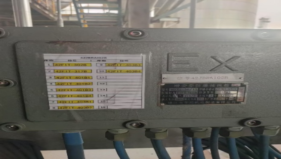
Tag/Loop: 42FIT-302B (AI-302B-01)
Measured Variable: Volumetric flow via primary element (DeltaBar/DP primary device) + secondary DP transmitter
Medium/Service: Process liquid (clean to mildly fouling)
Design Range: Sized for normal operating flow; DP transmitter span configured per orifice/DeltaBar calculation (details in P&ID)
Power/Signal: 24 VDC two-wire, 4–20 mA + HART, single-ended shield grounding
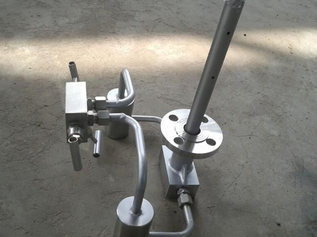
Impulse Lines & Manifold: Two SS impulse lines; standard three-valve manifold (H/L isolate + equalize)
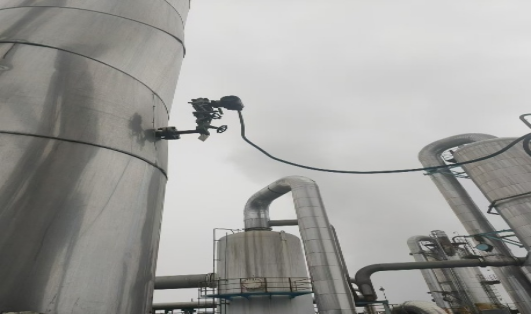
Environment: Outdoor tray routing, UV/rain exposure; junction box (JB) and transmitter at grade
Recent Work: No transmitter change; suspected historical field splice during minor routing change
3. Failure Symptoms
Timestamp (UTC+8): 2025-08-10 09:33–09:35 incipient fluctuation; 09:35 PV dropped to zero
DCS Alarm: BAD PV / Lo-signal
Local Indicator: Transmitter display off
Operator Observation: No apparent process upset; control valve steady, upstream/downstream pressures within normal band
4. Safety & Work Permits
Work under valid hot/cold work permit and LOTO as needed.
Verify loop service is non-hazardous; if hazardous, use SIS/MOC protocol and gas test.
Ladder/height PPE, cut-resistant gloves, eye protection.
Confirm control strategy in MANUAL before equalizing/closing manifold valves.

5. Diagnostic Methodology and Evidence
5.1 Electrical Chain (Power/Signal)
Objective: Determine where 24 VDC is lost.
| Checkpoint | Test | Observed Value | Interpretation |
|---|---|---|---|
| Control room isolator | Loop VDC | 24.0–24.1 V | OK (supply healthy) |
| JB#42-2 (X1 +/-) | Loop VDC | 23.8 V (stable) | Power present at JB |
| Transmitter terminals | Loop VDC | 0.6 V (unstable) | Voltage collapse between JB and TX |
| Transmitter output | Loop mA | ≈0 mA | Consistent with PV=0 / no power |
Finding: Voltage drop exists between JB and transmitter.
5.2 Cable/Continuity & Shielding
Visual on tray section #C-7: found non-standard inline splice (~4.3 m from TX). Copper strands blackened/oxidized, heat-shrink brittle, no sealing gland, no drip loop.
Continuity test across splice showed intermittent open under light bending.
5.3 Process Side (Impulse & Manifold)
Prior to electrical repair, manifold left isolated; no attempt to force PV.
After restoration (see §6), manifold operations conducted (see Appendix B). ΔP and PV corresponded to expected flow, confirming no impulse blockage.
6. Corrective Actions (As-Built)
Remove corroded splice and recover clean conductor to bright metal.
Re-termination: cold-pressed ferrules; dual-wall adhesive heat-shrink (2× overlap) over joint.
Ingress protection: added IP67 inline gland; formed drip loop; secured to tray with UV-rated ties.
Mechanical QC: Pull test ≥ 30 N per conductor; visual check for full barrel fill, no stray strands.
Shield & Ground: Shield continuity preserved; single-point ground at JB maintained.
Documentation: Marked tray section C-7 and JB X1; updated loop drawing and cable schedule.
7. Verification & Restoration
Post-repair readings (power off process equalized): 24.0 V at TX; loop current ~4.0 mA (LRV).
Return to service (manifold per Appendix B):
Equalize closed → H/L isolates opened: PV climbed smoothly with process.
DCS trend stabilized; loop current ~12.1 mA at observed flow, PV = expected ±0.3%.
24-hour soak: No alarms, no drift; no moisture ingress observed at new joint.
8. Root Cause
Outdoor, non-standard inline splice in cable segment (JB→TX) suffered environmental ingress (rain/condensation) and conductor oxidation, leading to an intermittent open circuit and loss of loop power.
Contributing factors
No IP-rated enclosure or sealing; no adhesive heat-shrink.
No drip loop; water path along cable sheath.
Splice location unmarked; not recorded in drawings.
9. Preventive Actions & Lessons Learned
9.1 Wiring & Materials Standard
Prohibit open splices in tray. Use IP67 junction box + terminal strip when extension is unavoidable.
Conductors: tinned, fine-strand copper; cold-pressed ferrules; torque per terminal spec; dual-wall heat-shrink for all field joints.
Routing: enforce drip loops, UV-rated ties, bend radius ≥ 8× OD.
9.2 Inspection & Testing
Quarterly sampling of outdoor analog loops (≥20%):
Insulation ≥ 20 MΩ @ 500 V (de-energized)
Loop resistance baseline vs. design
Shield continuity & single-point ground check
Add pull-test and photo record to closeout checklist.
9.3 Process/Operations
Maintain a laminated Three-Valve Manifold Card at the transmitter (Appendix B).
Capture before/after trends (PV/mA/status) and attach to the work order.
9.4 Documentation & Training
Update loop drawings, cable schedules, tray section IDs.
Toolbox talk: “Why open splices fail outdoors” (moisture + capillary action + galvanic/oxide growth).
10. Appendices
Appendix A — DP Primary Element Quick Notes
Straight-run: follow vendor/ISO guidance (typical: ≥10D upstream, ≥5D downstream unless straightener used).
Tappings: high-pressure tapping upstream, low downstream; keep impulse lines short, level, and heat-traced if needed.
Mounting: orient transmitter to minimize gas pockets (liquid service) or condensate pools (gas/steam with seals).
Appendix B — Three-Valve Manifold Operation Card
To return to service after maintenance
Verify downstream isolation closed; transmitter power healthy.
Ensure equalize OPEN, H & L isolates CLOSED.
Slowly OPEN H isolate, then SLOWLY OPEN L isolate (monitor PV rise).
CLOSE equalize.
Check leaks; confirm PV stable and matches expected.
Hand back to operations; restore control mode.
Reverse sequence for safe isolation: H & L CLOSE → equalize OPEN → depressurize via drain as permitted.
Appendix C — Static Pressure Effect (Heads-Up)
High static pressure can bias DP readings via transmitter mechanics/fluid properties.
Mitigation: live-zero checks, apply vendor static pressure compensation, verify span under operating pressure where applicable.
Appendix D — Maintenance Record (Template)
Work Order / Date / Techs: ______ / ______ / ______
Process Conditions (medium / T / P / valve): __________________________
Electrical Data:
Control-room supply: __ VDC
JB terminal X1 +/-: __ VDC
TX terminal +/-: __ VDC; Output: __ mA
Cable/Shield Checks: continuity __ / insulation __ MΩ @ __ V; shield ground (□ single-point / □ issue)
Manifold Actions: followed card (□ yes / □ no); ΔP before/after equalization: __ → __ kPa
Findings (with photo IDs): __________________________________________
Corrective Actions/Materials (ferrule, heat-shrink, gland, torque, pull-test): ___________________
Verification: PV __ ; mA __ ; 1-h trend stable (□) / notes: ____________
Closeout: drawings updated (□), training note filed (□)
11. Takeaways (One-Page for Toolbox Talk)
Symptom: PV=0, display off → suspect power path first.
Fast triage: control room → JB → TX voltage ladder; never skip measurements.
Outdoor splices fail; use IP67+ practices or proper JB.
Document everything: data tables, photos, trend captures—future you will thank present you.