Differential pressure (DP) transmitters are the workhorses behind level, flow, and filter monitoring across process plants. Yet most performance problems trace back to fundamentals—mounting, impulse line routing, wiring, and commissioning. This guide distills field-proven practices so your DP devices start accurate and stay reliable.
1) How a DP Transmitter Works (Quick refresher)
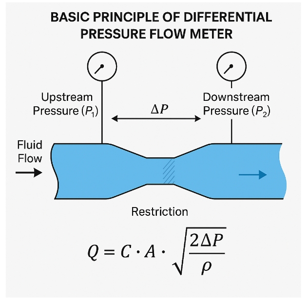
A DP transmitter measures the pressure difference between its high-pressure (HP) and low-pressure (LP) ports. In flow applications with primary elements (orifice, Venturi, pitot, V-cone, etc.), DP ∝ flow², so the output often uses square-root extraction. For level with wet leg/dry leg arrangements, the “zero” reflects static head in the impulse lines.
2) Selection Checklist (before you touch a wrench)
Range & turndown: Choose a span that places normal operation in the middle 30–80% of range.
Static pressure & over-pressure: Verify ratings against the process maximums.
Temperature window: Consider ambient and process temperature; add remote seals/capillaries and fill fluid where needed.
Process connection & materials: Match wetted materials (diaphragm, manifold, impulse tubing) to the medium.
Output & comms: 4–20 mA (two-wire) with HART is standard; plan for local display as needed.
Hazardous area & IP rating: Specify Ex protection and enclosure ingress protection per site classification.
3) Mechanical Installation: the golden rules
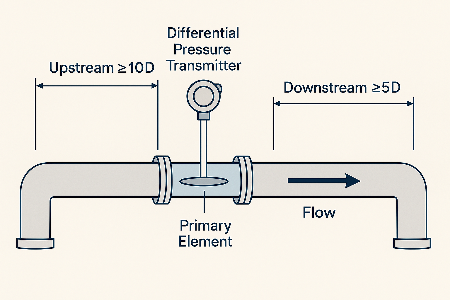
3.1 Impulse line routing
Keep HP and LP equal length and diameter with symmetrical bends.
Avoid pockets that trap gas in liquid legs or liquid in gas legs; maintain a continuous slope toward the transmitter.
Mount the transmitter below the process line for liquids/steam (to keep impulse lines filled), and above for gases (to drain condensate back).
Support tubing and the transmitter to reduce vibration.
3.2 Manifolds & isolation
Use a three-valve manifold (HP/LP isolation + balance) as standard.
For steam, install two equal-height condensate (seal) pots—one on each leg—to ensure the same hydrostatic head on HP and LP.
In erosive/dirty service, add root valves and flushing ports.
3.3 Special: steam service
Two seal pots at the same elevation; transmitter below the line.
Insulate/heat-trace as needed to prevent freezing and to stabilize density in wet legs.
Pre-fill/condition the legs before putting into service.
4) Electrical Wiring & Grounding (two-wire 4–20 mA)
Observe the polarity: +24 VDC on the loop “+”, return on “–”.
Use twisted, shielded pair; terminate the shield at one end only (usually the DCS end) to avoid ground loops.
Respect the supply voltage and loop load from the datasheet (the max total loop resistance depends on supply).
Keep power, VFD, and relay cables physically separated; cross at 90° if crossing is unavoidable.
For hazardous areas, use certified intrinsic safety barriers or isolators.
5) Commissioning & Zeroing (SOP you can trust)
5.1 Putting a DP into service with a 3-valve manifold
Verify isolation from the process; check tags and LOTO.
Open both vent/bleed points to purge air/contaminants; then close them.
Open the balance valve, keep HP/LP isolation closed.
Slowly open HP isolation, then LP isolation to fill/pressurize impulse lines.
Close the balance valve; check for leaks and a stable reading.
5.2 Online zero check
Close HP and LP isolations.
Open the balance valve (HP = LP); wait for the output to stabilize near zero.
If needed, perform a fine zero trim (local or via HART).
Close the balance valve; re-open HP and LP isolations in sequence.
Tip: Ensure both legs are at the same temperature (steam/wet leg) before zero trim; density differences create false zero shifts.
5.3 Span/range elevation & depression
For level and wet-leg applications, calculate the static head and apply elevation/depression correctly in the configuration rather than forcing large zero trims.
5.4 Square-root extraction for flow
Enable square-root either in the transmitter or in the control system (not both).
Configure a sensible low-flow cutoff to prevent noise and hunting at near-zero DP.
6) Verification, Maintenance & Reliability
Periodic loop check: Source/simulate 4–20 mA; verify DCS scaling.
Impulse line health: Look for blockage, leaks, or condensation errors; keep strainers clean upstream of primary elements.
Environment: Check for water ingress, corrosion at glands, UV/heat damage to cabling.
Freezing/boiling risks: Insulate or heat-trace as required.
Re-zero policy: After significant temperature swings, leg maintenance, or transmitter replacement.
7) Troubleshooting (symptom → likely cause → fix)
Output drifts slowly → Wet-leg temperature change or unequal seal pot levels → Refill/level seal pots; improve insulation.
Noisy signal on low DP → EMI, poor grounding, or two-phase flow → Fix shield termination; improve cable segregation; install pulsation dampers or adjust low-flow cutoff.
Reading offset after shutdown → Trapped gas/liquid or manifold left unbalanced → Re-establish proper leg fill; follow SOP; re-zero.
Zero cannot be achieved → Blocked impulse line or wrong elevation/depression settings → Clean/flush lines; correct configuration.
Span nonlinearity in flow → Square-root applied twice or wrong primary-element coefficients → Apply square-root once; verify ΔP-to-flow constants.
8) Quick Field Checklists
Pre-install
Datasheet matches tag (range, static rating, materials, Ex, IP)
Manifold, root valves, seal pots (if steam) on hand
Mounting location chosen for correct elevation and access
Pre-energize
Correct loop polarity and voltage
Shield bonded at one end; insulation resistance acceptable
Cable separation from high-noise sources
Startup
Manifold steps followed (isolate → balance → pressurize → debalance)
Zero verified under equalized legs
Square-root/low-flow settings confirmed (flow service)
Closing thoughts
Get the mechanics (routing, elevation, seal pots) and basics (wiring, grounding, SOP) right, and most “mysterious” DP errors disappear. Build these practices into your site standards and job cards so every install behaves like your best one.