In industrial automation, sensors are essential for detecting position, presence, distance, or motion. Among the most common types are three-wire DC sensors, typically categorized as NPN (sinking) or PNP (sourcing). Although they perform similar functions, they differ significantly in wiring logic and compatibility with control systems such as PLCs.
Understanding the difference between NPN and PNP wiring is vital to ensure correct installation, avoid damage, and maintain reliable operation.
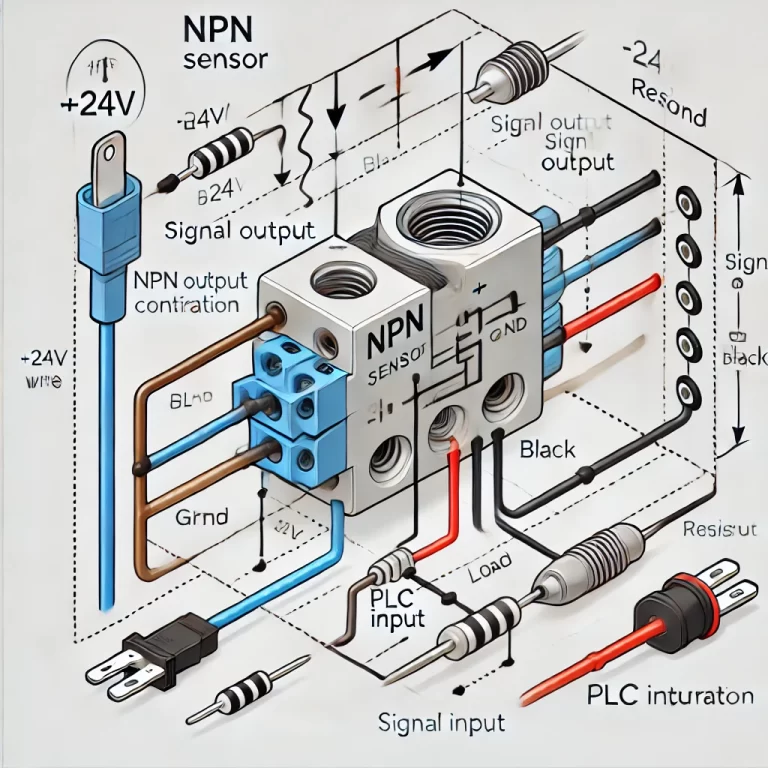
🔍 1. What Are NPN and PNP Sensors?
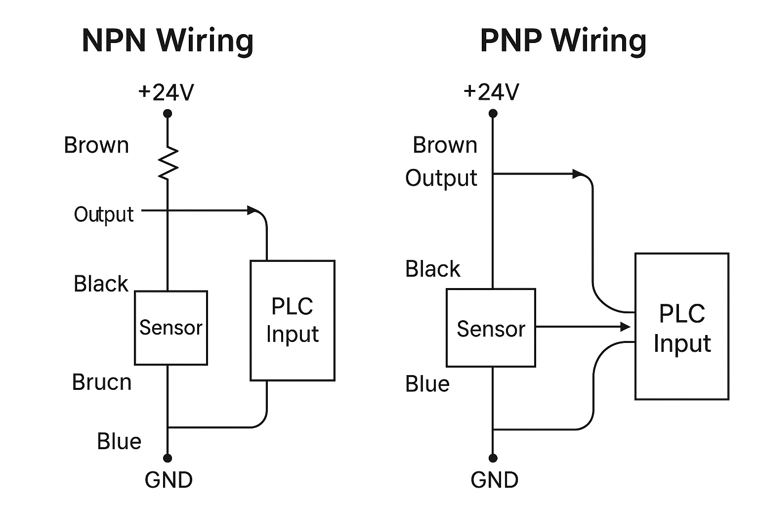
Both NPN and PNP sensors are types of transistor-output proximity switches (e.g., inductive, capacitive, photoelectric sensors). The terms “NPN” and “PNP” refer to the internal transistor configuration that determines how current flows when the sensor detects a target.
Type | Output Type | Switching Logic | Current Flow Direction |
---|---|---|---|
NPN | Sinking | Connects load to GND (0V) | From load → sensor → GND |
PNP | Sourcing | Connects load to +V (24V) | From sensor → load → GND |
Key takeaway:
NPN sensors pull the output to ground when activated.
PNP sensors supply voltage to the output when activated.
⚙️ 2. Working Principle and Wiring
NPN Sensor (Sinking Output)
When the NPN sensor detects a target, the internal transistor closes to GND. The output line is connected to 0V, allowing current to flow from the load through the sensor to ground.
Typical Wiring:
Brown = +24V
Blue = 0V (Ground)
Black = Signal Output (connects to PLC input)
🟢 Connect the load between output and +24V.
+24V —-[Load/PLC Input]—- Black (Output)
|
Sensor
Brown: +24V Blue: GND
PNP Sensor (Sourcing Output)
In a PNP sensor, when activated, the transistor connects the output to +24V. The output line supplies voltage to the load, which must be connected to GND.
Typical Wiring:
Brown = +24V
Blue = 0V (Ground)
Black = Signal Output (connects to PLC input)
🟢 Connect the load between output and ground.
+24V —- Sensor
|
Black (Output) —-[Load/PLC Input]—- GND
Brown: +24V Blue: GND
🖼️ 3. Suggested Wiring Diagrams
To visualize the difference clearly, you can use the following diagram format in your technical materials or training manuals:
🔹 NPN Wiring Schematic
[PLC Input]——[Pull-up resistor]——+24V
|
Black (Output) —— Sensor
| |
Brown Blue
+24V GND
🔹 PNP Wiring Schematic
+24V —— Brown
|
Sensor —— Black (Output) ——[PLC Input]
|
Blue —— GND
We recommend labeling wire colors clearly (brown, blue, black), and indicating the current flow direction and switching behavior using arrows.
🌐 4. Application Scenarios and Compatibility
✅ Choosing Between NPN and PNP:
Selection Criteria | Recommended Type |
---|---|
Using a PLC with sourcing inputs | NPN |
Using a PLC with sinking inputs | PNP |
Most European equipment | PNP |
Most Asian (Japanese) equipment | NPN |
Uncertain input type on controller | PNP (safer default in many cases) |
If your PLC input card requires current to sink (receive current), use PNP.
If it needs to source current (send out current), use NPN.
⚠️ 5. Common Wiring Mistakes
Miswiring NPN and PNP sensors is one of the most frequent causes of:
Sensor not triggering the PLC
Short circuits or blown inputs
False triggering due to floating signals
Typical Mistakes:
Reversing brown and blue wires (power and ground)
Connecting NPN sensor output to a sourcing input (incompatible)
Mixing NPN and PNP types in the same input bank of a PLC
💡 Tip: Never mix NPN and PNP sensors on the same PLC input module unless the module is designed to support both (rare).
🧪 6. How to Identify Sensor Type
If the datasheet or label is missing, you can identify the sensor type using a multimeter:
Power the sensor with 24V (brown to +24V, blue to 0V).
Measure voltage at the black wire (output) with no object:
PNP: Should read ~0V (low) when inactive, ~24V (high) when triggered.
NPN: Should read ~24V (high) when inactive, ~0V (low) when triggered.
Markings to look for on sensor label:
“Sinking output” → NPN
“Sourcing output” → PNP
Circuit diagram symbol showing connection to GND or +V
🧭 7. Selection Guide (Checklist)
Before finalizing sensor selection, confirm the following:
✅ Is the controller/PLC compatible with the output type?
✅ Are all sensors in the system of the same type (NPN or PNP)?
✅ Are the wire colors standard? (Brown = +24V, Blue = GND, Black = Output)
✅ Are the power supply and input voltage levels compatible (typically 10–30V DC)?
✅ Are you using shielded cables for long runs or noisy environments?
✅ 8. Conclusion: Key Differences Summary
Feature | NPN Sensor | PNP Sensor |
---|---|---|
Output behavior | Switches to Ground (0V) | Switches to +24V |
Current flow | From load → sensor → ground | From sensor → load → ground |
Output type | Sinking | Sourcing |
Wiring requirement | Load between output and +V | Load between output and GND |
PLC compatibility | Sourcing input cards | Sinking input cards |
Common regions | Japan, China, Korea | Europe, North America |
When in doubt, consult the PLC manufacturer’s input module documentation or sensor wiring diagram to determine compatibility.