1. Introduction
In the chemical industry, a process package—often referred to as a technology package or engineering design package—is the foundational set of documents and specifications for designing, constructing, and operating a chemical production unit. It plays a central role in ensuring safety, operability, and efficiency throughout the plant lifecycle.
The development of a process package is a complex, multidisciplinary task involving professionals from process engineering, chemical analysis, instrumentation and control, safety and environmental engineering, and other domains. This document outlines the typical components, scope, and depth of a standard chemical process package.
2. Standard Components of a Process Package
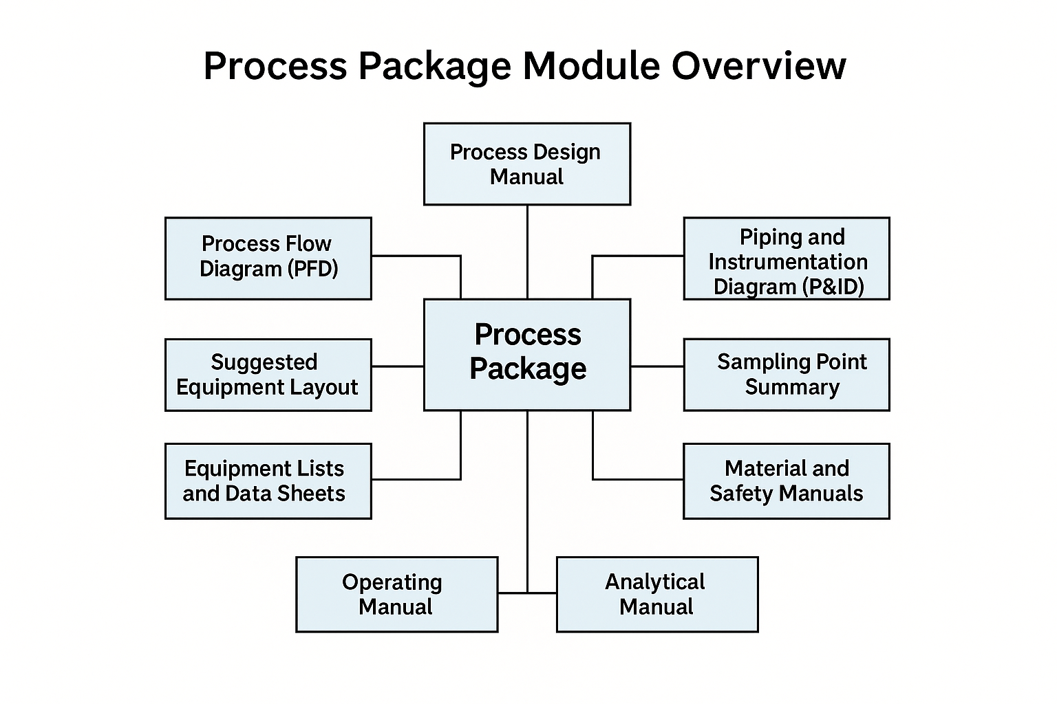
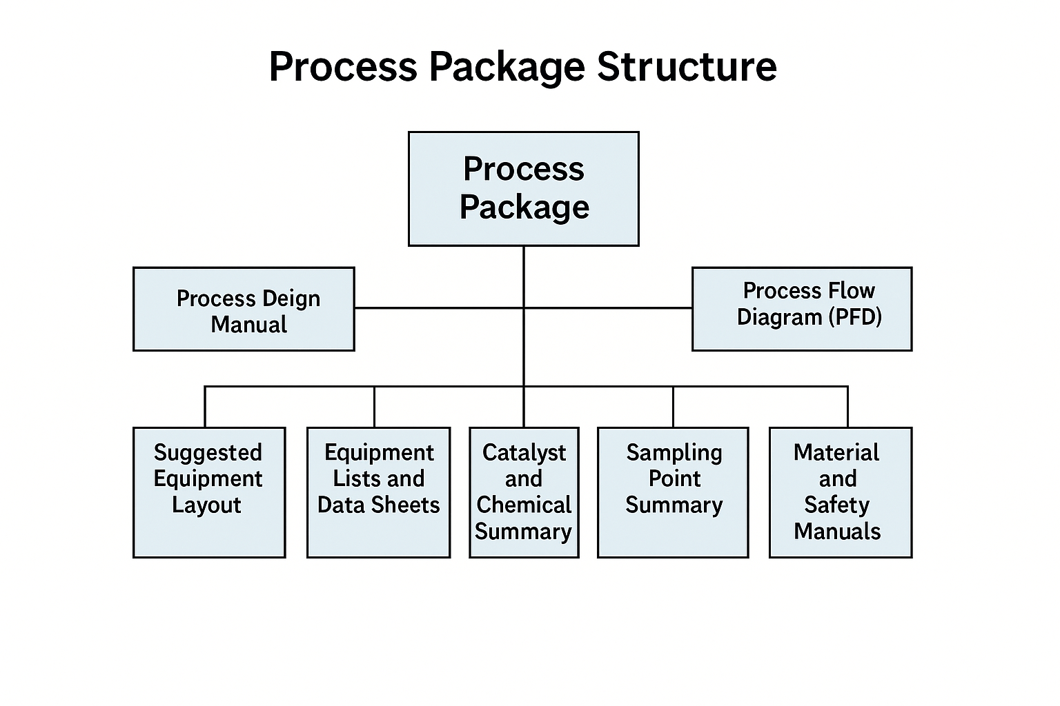
A complete process package generally includes the following documents and data:
Process Design Manual
Process Flow Diagram (PFD)
Piping and Instrumentation Diagram (P&ID)
Suggested Equipment Layout
Equipment List and Data Sheets
Catalyst and Chemical Summary
Sampling Point Summary
Material and Safety Manuals
Operating Manual
Physical Property Data
Supporting Calculations and Design Bases
Each section provides critical information for downstream engineering design, construction, commissioning, and operation.
3. Process Design Manual
The process design manual is a comprehensive document that describes the design basis, process philosophy, and key operating parameters. It usually includes:
3.1 Overview
Process selection and technology features
Design capacity (e.g., tons/year or m³/year), operating hours per year
Plant operating philosophy (e.g., 5 shifts, 3 operations)
Process unit breakdown (by section or subsystem)
3.2 Environmental Impact
List of equipment generating wastewater, waste gas, and solid waste
Quantitative estimates of emissions and disposal methods
Preliminary plans for waste treatment and resource recovery
3.3 Design Basis
Feedstock and chemical specifications
Utility specifications (steam, water, electricity, air)
3.4 Process Description
Process principles and reactions (including main and side reactions)
Catalyst types and specifications
Section-by-section or system-based process descriptions (e.g., reactor, distillation column, compressor)
3.5 Operating Conditions and Controls
Key process conditions: temperature, pressure, flowrate, composition
Control indicators and target values
Product specification and yield expectations (guaranteed and expected)
Raw material and utility consumption figures
3.6 Equipment Selection Philosophy
Justification for key equipment types (e.g., heat exchangers, reactors, pumps)
Notes on materials of construction and design considerations
Control and safety interlock system logic
4. Process Flow Diagrams (PFDs)
The PFD provides a high-level visual representation of the material flow and energy exchange within the process. It typically includes:
Major equipment symbols and tag numbers
Stream numbers with flow direction
Operating conditions (flowrate, temperature, pressure, composition)
Utility interfaces
Material balance tables
PFDs serve as a foundation for developing P&IDs and process simulations.
5. Piping and Instrumentation Diagrams (P&IDs)
P&IDs provide detailed information on the piping, instrumentation, and control systems. They include:
Equipment symbols and interconnections
Pipe specifications and line numbers
Instrumentation, valves, and control loops
Safety systems and interlocks
Utility piping and tie-in points
These diagrams are essential for construction, commissioning, and maintenance planning.
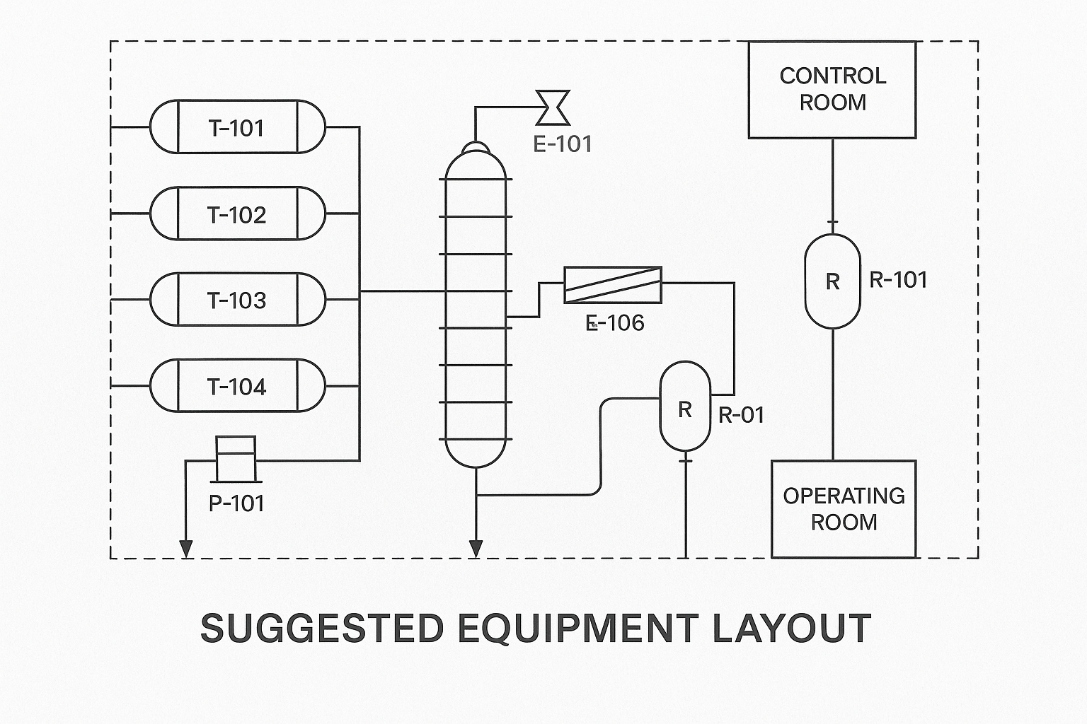
6. Suggested Equipment Layout
The layout drawing offers a reference for equipment positioning and space allocation. While preliminary in nature, it should cover:
Building and structure outlines with reference dimensions
Relative positions and elevations of major equipment
Special height requirements for gravity-driven systems or safety
Locations of control rooms and operating stations
This layout helps ensure proper access, maintenance space, and safety zoning.
7. Equipment Lists and Data Sheets
These documents provide structured technical information for procurement and design:
Equipment List: A master list with tag numbers, names, types, and quantities
Data Sheets: Detailed operating parameters, design conditions, materials of construction, mechanical details, and reference sketches
They are prepared for major equipment such as:
Reactors
Columns
Heat exchangers
Pumps and compressors
Storage tanks
Filters
8. Catalyst and Chemical Summary
For catalytic or reactive processes, a table is provided listing:
Catalyst name, grade, and supplier
Loading quantity and replacement schedule
Required auxiliary chemicals (e.g., neutralizers, inhibitors)
Safety and storage requirements
9. Sampling Point Summary
This summary helps design the analytical control system and laboratory interface. It includes:
Sampling point location and tag
Type of sample (gas, liquid, slurry)
Analysis items and frequency
Sample collection and handling method
Safety precautions
This ensures traceability and effective process monitoring.
10. Safety, Health, and Environmental Manual
The safety manual addresses risks related to flammability, toxicity, explosions, and occupational exposure.
Contents include:
Process hazard analysis
Fire and explosion prevention measures
Toxicity data of raw materials and products
Protective equipment recommendations (e.g., respirators, eye washers)
Emergency response requirements (e.g., venting systems, alarms)
A well-prepared safety manual significantly reduces risk during commissioning and operation.
11. Operating Manual
Typically prepared by the licensor or engineering contractor after design completion, the operating manual covers:
Process philosophy and control logic
Startup, shutdown, and emergency operation procedures
Key operating parameters per system (reactor, column, etc.)
Checklists for inspection and pre-commissioning
Equipment lubrication, flushing, purging, and calibration steps
It ensures consistent, safe operation and facilitates staff training.
12. Analytical Manual
This manual outlines methods and responsibilities for process analysis. It includes:
Laboratory workflow and organizational responsibilities
Sampling design principles and frequency
Sample preparation and storage procedures
Analytical methods for feedstock, intermediates, and products
Instrument calibration and quality control guidance
Clear analytical procedures are critical for quality assurance and process optimization.
13. Physical Property Data and Calculations
A comprehensive process package often includes a property data booklet and associated calculation sheets:
Thermophysical properties (density, viscosity, heat capacity)
Vapor-liquid equilibrium data
Utility demand calculations
Pressure drop and line sizing
Equipment rating and simulation results
This technical foundation supports further engineering design (basic/detailed), simulation, and optimization.
14. Quality Control and Documentation Standards
Process package documents must adhere to internal quality standards and international codes. Key principles include:
Use of standardized templates
Revision control
Document numbering system
Multidisciplinary review and sign-off
Consistency ensures all parties (engineering, construction, and operators) can rely on the information provided.
15. Conclusion
A well-developed process package is not merely a set of drawings—it’s a comprehensive technical solution that enables safe, efficient, and economically viable chemical production. From process flows to safety strategies, each component ensures that the plant can be built and operated with confidence.
As chemical production becomes more sophisticated, the importance of standardized, detailed, and accessible process packages will only increase. Whether for internal design, technology licensing, or third-party review, a strong process package is the cornerstone of chemical engineering excellence.