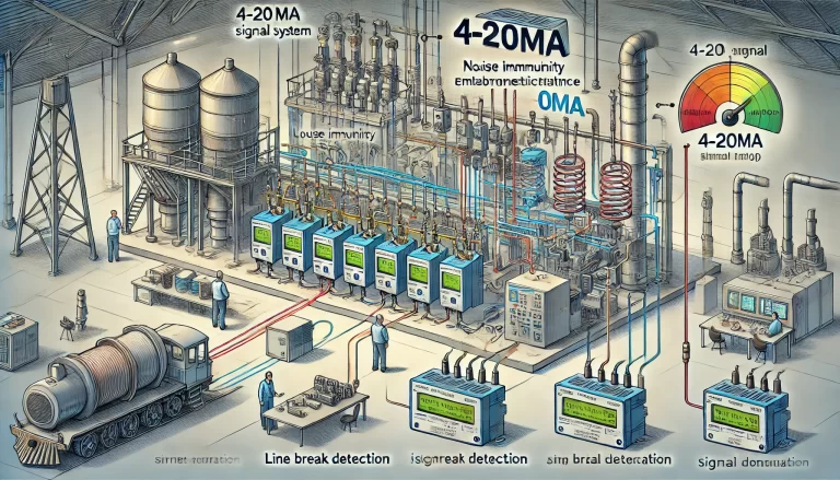
Introduction
In industrial automation, the choice of signal transmission is critical to the reliability and stability of the control system. Among the various methods available, the 4-20mA current signal has become the de facto standard. But why is 4-20mA preferred over alternatives like 0-20mA or 0-10V?
This article explores the technical, practical, and safety reasons behind the widespread use of 4-20mA signals in industrial environments. Through real-world examples and engineering analysis, we’ll clarify why 4-20mA is more than just a convention — it’s an engineering necessity.

1. Background: Signal Transmission in Automation
Sensors used in industrial automation — such as those for level, pressure, temperature, and flow — convert physical parameters into electrical signals. These signals are transmitted to control systems like PLCs or DCSs for further processing.
Common analog signal types include:
Current: 4-20mA, 0-20mA
Voltage: 0-10V, 1-5V
So why has 4-20mA become the “golden standard”? Let’s explore.

2. Why 4-20mA?
2.1 Live Zero: Built-in Fault Detection
If a 0mA signal is used to indicate the minimum measured value (e.g., 0°C), it becomes impossible to distinguish between a true measurement and a line break. Both cases would show 0mA.
By contrast, 4-20mA introduces a concept called “live zero”:
4mA represents the minimum valid measurement
<3.6mA typically indicates a fault (open circuit, short, or failure)
20.5mA may indicate over-range or sensor failure
This approach enables the system to detect faults automatically. For example, in a chemical plant, a sudden 0mA reading would trigger an alarm to inspect wiring, rather than misinterpreting it as a low temperature.

2.2 Strong Noise Immunity: Reliable Over Long Distances
Industrial environments are full of electromagnetic interference from motors, VFDs, and other equipment. Voltage signals (e.g., 0-10V) are susceptible to:
Electromagnetic noise
Voltage drop over long cable runs
However, current signals remain stable because the current in a closed loop is unaffected by resistance or cable length, as long as the power supply voltage is sufficient (I = V/R).
In large factories with cable lengths exceeding 1 km, a 4-20mA loop ensures reliable transmission, while a voltage signal could degrade significantly.
2.3 Two-Wire Power Supply: Simplified Wiring
Many transmitters (e.g., pressure or temperature) use a two-wire loop where the same two conductors provide both:
Power (typically 24VDC)
Signal (4-20mA)
This reduces wiring complexity and is especially advantageous in:
Remote installations
Hazardous areas
2.4 Low Power Consumption: Safe for Hazardous Areas
At 24VDC and 20mA, the maximum power consumption is only 0.48W — low enough to meet intrinsic safety requirements in explosive environments such as:
Oil refineries
Chemical plants
Underground mines
Voltage-based systems often require higher power levels, increasing the risk of spark generation.

3. Why Not 0-20mA or 0-10V?
3.1 Limitations of 0-20mA
At 0mA, it’s impossible to distinguish whether:
The process variable is at the lower limit
There is a signal fault (e.g., wire break)
This lack of clarity can lead to delayed maintenance or incorrect system responses.
3.2 Limitations of 0-10V
Susceptible to noise: Especially over long distances in noisy industrial environments
Voltage drop: Affects measurement accuracy
Requires separate power lines: No loop-powered option like 4-20mA, leading to higher installation cost and complexity

4. Comparison Table
| Feature | 4-20mA | 0-20mA | 0-10V |
|---|---|---|---|
| Fault detection (Live Zero) | ✅ Yes | ❌ No | ❌ No |
| Noise immunity | ✅ High | ✅ High | ❌ Low |
| Long-distance reliability | ✅ Excellent | ✅ Excellent | ❌ Poor |
| Loop-powered (2-wire) | ✅ Supported | ✅ Supported | ❌ Not supported |
| Suitable for hazardous areas | ✅ Yes (low power) | ✅ Yes (low power) | ❌ Limited |
5. Historical Perspective
The 4-20mA standard didn’t arise by chance. In earlier pneumatic systems, 3-15 psi signals were used — also representing a 1:5 ratio. The 4-20mA range preserved this scaling and helped engineers transition from pneumatic to electronic control systems.
Decades of engineering practice have proven 4-20mA to be reliable, cost-effective, and suitable for virtually all process industries.

6. Conclusion
The 4-20mA current loop remains a foundational element in industrial signal transmission due to its:
Built-in fault detection
Strong resistance to interference
Simplified two-wire wiring
Low power consumption and explosion safety
Its advantages are not merely theoretical — they’re the result of decades of real-world engineering success.
If you’re building or upgrading an automation system, understanding the reasons behind the 4-20mA standard is key to making informed, reliable, and safe design decisions.
