Introduction
In Safety Instrumented Systems (SIS), it is strongly discouraged to route Digital Input (DI) and Digital Output (DO) signals through the same multi-core cable. While this may seem convenient or cost-saving, it is considered poor engineering practice and is typically unacceptable in systems that require high integrity and reliability. Below is a detailed technical explanation of the risks involved.
1. Risks of Shared Cabling
1.1 Electrical Interference (Crosstalk)
DO signals—especially when used to drive relays, solenoid valves, or motor starters—can generate significant voltage and current transients, particularly when switching inductive loads. These transients can:
Couple into adjacent DI signal lines via capacitive or inductive coupling.
Cause false state transitions (e.g., 0 → 1 or 1 → 0) on DI lines.
Such false signals may lead to:
Unintended shutdowns or false trips (e.g., a valve falsely reported as closed could trigger an incorrect start).
Failure to detect hazardous conditions, if a high-pressure signal or emergency stop is suppressed by interference.
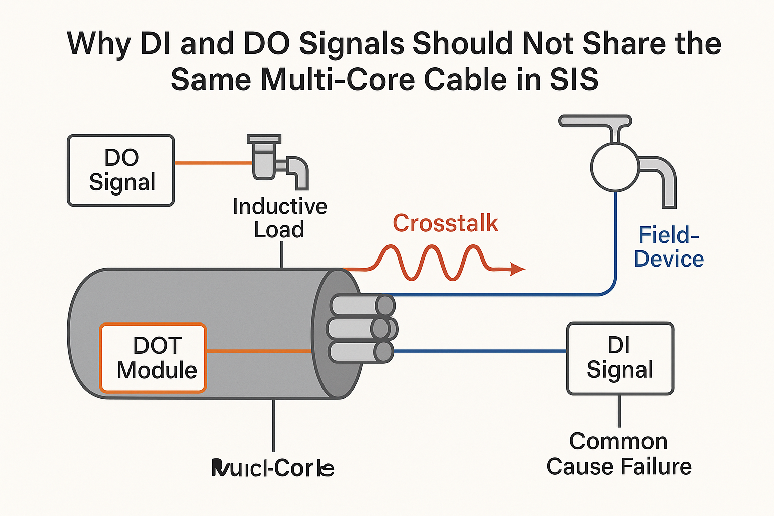
1.2 Common Cause Failures
If a shared cable is damaged—by crushing, water ingress, corrosion, or short circuit—it can simultaneously impact both DI and DO circuits, violating the SIS design principle of fault independence.
This increases the risk of common cause failures, where a single cable fault can disable multiple safety functions at once—posing serious safety hazards.
1.3 Ground Loops and Potential Differences
If DI and DO signals are connected to different field devices with different ground potentials (common in industrial settings), a ground loop can form through the cable shield or return path, injecting noise into sensitive DI signals.
1.4 Troubleshooting and Maintenance Difficulties
Shared cabling complicates fault isolation and diagnostics.
Testing or maintaining a DO loop could inadvertently affect DI inputs, making the system unstable or unsafe during maintenance.
2. SIS Standards and Best Practices
2.1 IEC 61511 / ISA 84 Requirements
While the standards do not explicitly forbid shared cabling, they enforce the following key principles:
Avoid common cause failures (Clause 11.2.4): Shared cables violate this by introducing a single point of failure for multiple safety functions.
EMC Robustness (Clause 11.2.13): SIS circuits must withstand expected electromagnetic interference (EMI). Shared DI/DO cabling increases internal EMI risk.
Physical Separation: Encouraged between safety and non-safety loops, and between independent safety functions. DI and DO loops serve different safety functions and should be routed separately.
2.2 Good Engineering Practice (GEP)
DI signals (status monitoring) are vulnerable and must be protected from interference.
DO signals (actuation) are active sources of interference and should be isolated from DI.
GEP dictates that these two types of signals should be wired through separate, shielded cables with proper grounding.
3. Rare Exceptions (If Absolutely Necessary)
In rare, low-risk scenarios, shared cabling may be considered—but only under strict conditions:
Non-SIF signals: DI and DO signals do not belong to any Safety Instrumented Function (SIF), or are auxiliary low-risk functions within the same SIF.
Static DO signals: Outputs that switch very rarely and drive purely resistive loads.
High-grade cabling: Use of triple-shielded cables (individual pair shields + overall shield) with high-quality grounding.
EMC validation: Verified through testing or simulation that EMI will not compromise DI signal integrity.
Documented exception: Detailed records in the Safety Requirements Specification (SRS), with approval from all stakeholders via a Functional Safety Assessment (FSA).

4. Recommended Best Practices
| Signal Type | Recommended Cabling | Grounding | Additional Notes |
|---|---|---|---|
| DI | Twisted-pair shielded cables | Single-point grounding at controller | Avoid parallel runs with power cables |
| DO (Inductive) | Shielded cables | Load-end grounding (in some cases) | Add snubber circuits, freewheeling diodes, or MOVs |
| Routing | Physically separate cable trays or conduits | — | Avoid long parallel runs between DI and DO cables |
Conclusion
To achieve maximum safety and system reliability in SIS applications, DI and DO signals must be wired separately using independent shielded cables.
Sharing a multi-core cable introduces significant risks, including interference, diagnostic complexity, and common-cause failure—far outweighing any potential cost or space savings.
Any deviation from this rule must be thoroughly justified, tested, documented, and formally approved.