Differential pressure (DP) flow meters are widely used in industrial process control. When a DP flow meter shows no indication despite other equipment operating normally, it often signals either a measurement system issue or a process anomaly. This article analyzes two real-world cases and provides a structured troubleshooting guide.
✅ Case Study 1: No Flow Indication in Paraxylene Charging After Plant Startup
Background:
After the benzene cracking unit restarted from maintenance, the paraxylene charging flow showed no indication on the DP flow meter.
Maintenance engineers repeatedly inspected the transmitter and orifice plate measurement system but found no issues.
When draining the transmitter impulse lines, the flow indication briefly reappeared but later disappeared again.
Meanwhile, a rotameter measuring the same flow showed a stable indication, and the reactor temperature indicated that paraxylene was indeed being fed into the oxidizer.
Diagnosis:
A comprehensive inspection ruled out faults in the measurement system. Suspicion turned to the process fluid. A sample taken from the impulse line revealed significant stratification. Laboratory analysis confirmed excessive water contamination in the paraxylene feedstock—approximately 30% water content.
Since paraxylene and water have a large density difference (~100 g/L), and the impulse lines were long (~4 meters), the hydrostatic head from the density difference canceled out the differential pressure generated across the orifice plate. As a result, the DP transmitter could not detect flow.
Resolution:
The process department was notified to address the water contamination in the paraxylene feedstock. After corrective actions, the DP flow meter operated normally.
✅ Case Study 2: No Flow Indication in Fluidized Bed Water Supply
Background:
Operators reported no flow indication on the DP flow meter for the fluidized bed’s water supply, even though the gas bag level and reactor temperature suggested water was entering the system.
Diagnosis:
Maintenance personnel drained both the high-pressure and low-pressure sides of the DP transmitter.
The transmitter showed output from the low-pressure side, confirming the transmitter itself was functional.
However, draining the high-pressure side revealed poor flow through the impulse line, indicating a potential blockage.
A segmented inspection using compressed air showed no blockage from the transmitter flange to the three-valve manifold or from the manifold to the primary valve. The blockage was finally located in the primary isolation valve and orifice plate chamber.
Resolution:
The needle-type isolation valve could not be cleared, so a temporary shutdown was arranged to replace it with a ball valve. After replacement, the DP flow meter operated normally.
Recommendation: For water flow measurement, use ball valves for primary isolation to facilitate routine maintenance and blockage removal.
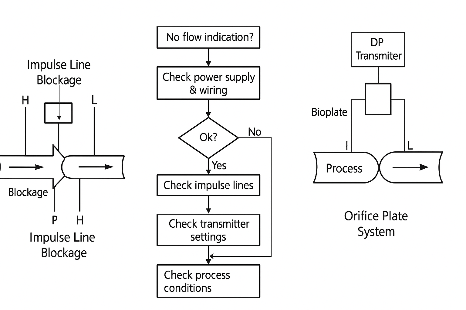
⚠️ Common Causes of No Flow Indication in DP Flow Meters
Instrument-Related Issues
Power supply failure or loose wiring
Impulse line blockage (condensate, debris, or freezing)
Transmitter malfunction or incorrect range configuration
Drain or vent valves left open
Improper zeroing or fixed 4mA output setting in smart transmitters
Process-Related Issues
No actual flow in the process pipeline
Fluid stratification in impulse lines (due to density differences)
Incomplete condensation in steam applications
Air or gas bubbles in the impulse lines
🔧 Step-by-Step Troubleshooting Guide
Verify Power Supply
Check if the transmitter display is active.
Use a multimeter to measure 24V DC at the power supply terminals and at the transmitter.
Check Electrical Connections
Inspect wiring for loose connections or corrosion.
Tighten terminal screws and clean oxidized contacts.
Inspect Impulse Lines
Drain impulse lines to remove condensate or air pockets.
Check for blockages by applying compressed air or flushing.
Check Transmitter Settings
Ensure the range and configuration match the process requirements.
Confirm the transmitter is not set to “fixed output” mode.
Simulate Differential Pressure
Temporarily open the low-pressure side vent to create a pressure differential.
Observe if the transmitter responds on the display.
Evaluate Process Conditions
Verify that there is actual flow in the pipeline.
Check for process fluid anomalies (e.g., density changes, phase separation).
💡 Best Practices for Prevention
Use short, well-routed impulse lines to minimize hydrostatic head effects.
Prefer ball valves over needle valves for primary isolation to simplify maintenance.
Regularly inspect and drain impulse lines in applications prone to condensation or sedimentation.
Implement heat tracing in cold environments to prevent freezing.