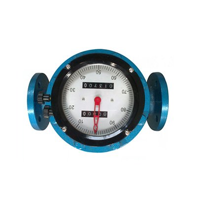
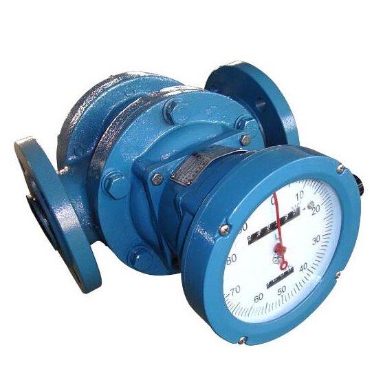
An oval gear flow meter is a highly accurate positive displacement meter that uses mechanical measuring elements to divide the flowing fluid into discrete, known volumes. It is widely used for measuring micro-flows and viscous media such as glue, honey, silicone, and lubricating grease.
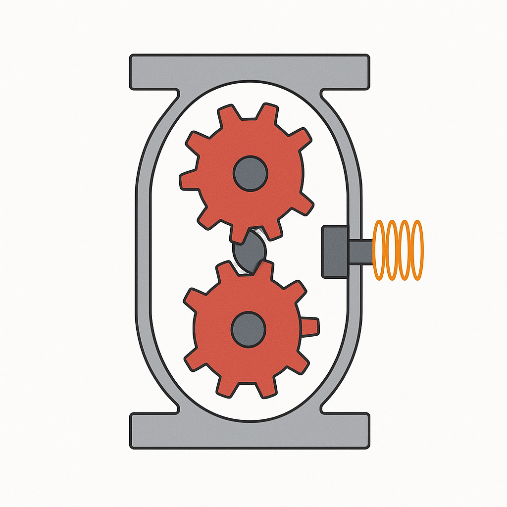
As fluid passes through the meter, the differential pressure between inlet and outlet drives a pair of oval gears to rotate. The cavities formed between the gear teeth are filled with fluid and discharged downstream.
A signal amplifier mounted on the meter housing detects the gear rotation via a sensor coil. Permanent magnets embedded in one of the gears generate magnetic flux as the gear rotates. The resulting magnetic flux variation induces a signal in the coil, which is amplified, shaped, and converted into pulses proportional to the flow rate. These pulses are processed by the meter electronics to display totalized volume and instantaneous flow.
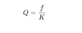
The flow meter’s K-factor defines the number of pulses per unit volume and can be expressed as:
Where:
Q = Instantaneous flow rate (L/min)
f = Pulse frequency (Hz)
K = Meter constant (pulses/L)
2. Fault Description
A newly installed oval gear flow meter initially operated normally. After running for a period, the flow display dropped to zero, and no fluid was discharged from the pipeline outlet.
3. Troubleshooting Process
Shut the upstream and downstream isolation valves.
Remove the flow meter for inspection.
Found debris lodged between the gears, preventing rotation.
Cleaned the debris and reassembled the meter.
Upon recommissioning, fluid flow was restored at the outlet, but the meter continued to display zero flow.
4. Root Cause Analysis
Oval gear flow meters use two meshing gears, but only one gear contains embedded permanent magnets. These magnets are critical for the sensor coil to detect rotation.
During reassembly, the two gears were installed in reverse positions. As a result, the sensor coil was unable to detect the magnetic field changes, and no pulse signals were generated, causing the display to remain at zero.
Solution: Swap the gear positions so that the gear with embedded magnets aligns with the sensor coil. After correct reassembly, the flow display returned to normal.
5. Lessons Learned and Recommendations
Issue
Cause
Solution
No flow display
Magnetic gear installed in incorrect position
Ensure magnetic gear faces the sensor coil during reassembly
Gear blockage by debris
Particles stuck between gear teeth
Install an upstream filter and clean it regularly
Potential gear damage by water hammer
Rapid valve operation causing fluid shockwaves
Operate valves slowly to prevent hydraulic shock
Additional Recommendations
Filtration: Install a fine mesh filter upstream to prevent fiber-like or particulate matter from entering the meter. Regularly clean the filter element.
Valve Operation: Open and close valves gradually to minimize water hammer that could damage gears.
Maintenance: Schedule maintenance every 3 months. During cleaning, take care not to damage internal components and always verify correct gear orientation upon reassembly.