In large-scale chemical, power, and petrochemical projects, piping and instrumentation may seem inconspicuous, but they are the “nerves” and “blood vessels” of the entire facility. When designed properly, systems operate reliably, require less maintenance, and deliver accurate data. When designed poorly, they become sources of error, constant alarms, frequent repairs, or even serious safety hazards.
This article discusses three key questions:
What constitutes a reasonable piping layout?
Where and how should instruments be installed?
How do gas and liquid piping systems differ in design?
1. Piping Design: More Than Just Connecting Two Points
1.1 Function over Form
New designers often prioritize symmetry and straight lines for a neat and logical drawing. But appearance doesn’t equate to usability or safety.
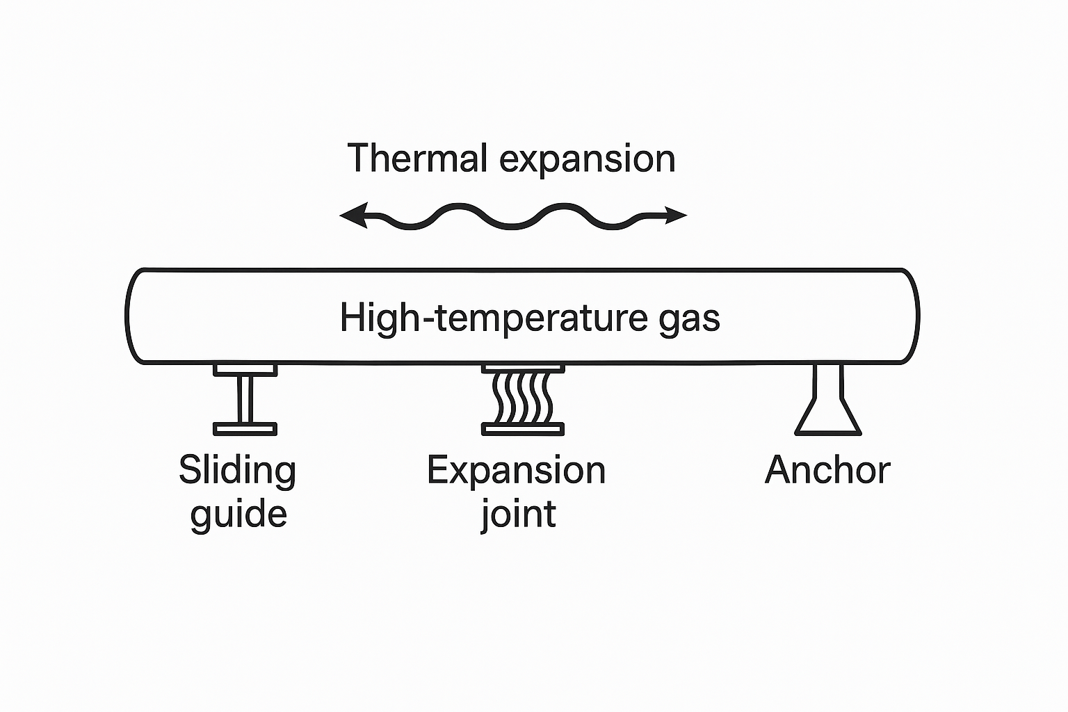
Example: A high-temperature, high-pressure steam line is routed directly from a boiler to a turbine with a clean and short path. While it looks perfect on paper, within months the flanges leak heavily due to thermal expansion stress—no expansion joints, no compensation for stress or water hammer pressure. The system fails under real operating conditions.
1.2 Maintainability Is Key
Installing valves flush against a wall or enclosing them in sealed panels may look clean, but makes maintenance nearly impossible. Good design considers who will service the equipment in 3 or 5 years—can they see it, reach it, and operate it safely?
2. Instrumentation Installation: Not Just a Control Engineer’s Job
2.1 You’re Measuring Meaning, Not Just Numbers
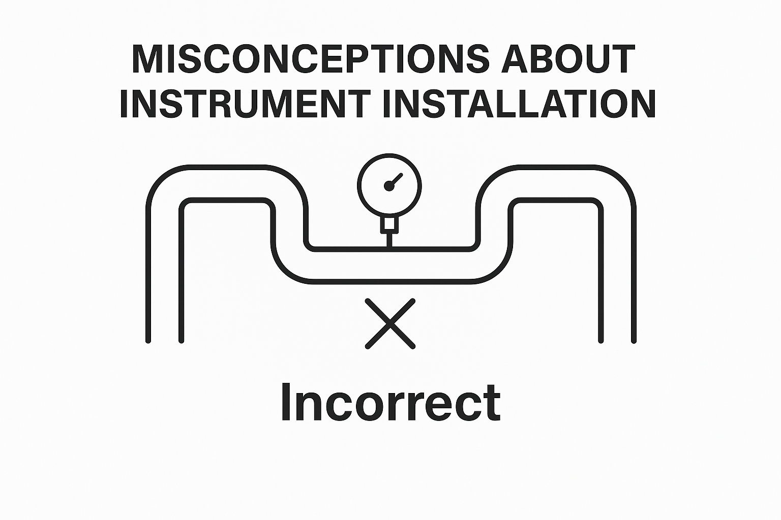
Installing a tuning fork level switch near the pipe inlet or with too shallow insertion may result in false high alarms on startup.
Installing a pressure gauge near pump or valve outlets causes it to swing erratically due to turbulence—rendering it useless for trend monitoring or control feedback.
Even a million-dollar instrument is worthless if installed in the wrong location.
2.2 Consider Vibration, Freezing, and Steam Hammer
Instruments mounted near vibrating machines or poorly fixed with zip ties will quickly fail.
Outdoor flowmeters that aren’t heat-traced may freeze and crack every winter. These are not technical failures, but failures in project accountability.
3. Key Differences Between Gas and Liquid Piping Systems
| Feature | Liquid Systems | Gas Systems |
|---|---|---|
| Flow Behavior | High density and stable viscosity; design focuses on pressure drop and cavitation | Low density and compressibility; design minimizes pressure loss and condensation |
| Pipe Slope | Drainage slope for liquid removal and freeze protection | Slope for condensate return to prevent compressor damage |
| Supports & Expansion | Less thermal movement; support prevents sagging; insulate to avoid cold bridges | High thermal expansion (e.g., 1000°C gas); requires sliding guides, expansion joints, electrical insulation |
| Vibration & Erosion | Risk of erosion at elbows and valves; use wear-resistant liners | Compressor pulsation causes turbulent flow; use flow straighteners and gaskets for vibration damping |
4. Pro Tips from Senior Engineers
Temperature Measurement at Heat Transition Points:
At the junction of heat-traced and insulated pipes, leave a 1-meter buffer zone for stable readings.Blowdown and Debris Prevention:
Always include purge ports with valves to prevent clogging of impulse lines due to welding slag or dust.Instrument Bypass & Inline Calibration:
Use a bypass line with dual valves and a drain to enable calibration without shutting down the process.Separate Signal Ground and Protective Ground:
Even when sensors share an I/O card, each shielded cable must return its shield to its own housing—shared grounding creates loop interference.
5. “Unwritten Rules” of the Industry
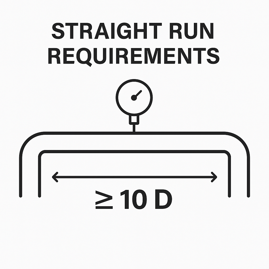
Straight Pipe Lengths Are Based on Fluid Dynamics, Not Guesswork
A typical spec might call for 10D (pipe diameter) upstream straight length, but on-site only 3D is available due to space. This severely compromises measurement accuracy, especially for vortex, ultrasonic, or differential pressure flowmeters.Misinterpretation of Instrument Data
Many control failures are caused not by faulty sensors, but by incorrect assumptions.
For instance, a condensate level sensor showing “full” during shutdown may be normal. Adjusting its alarm limits blindly can lead to false trips on startup.
6. Design Is Not a Showcase of Theoretical Perfection
Real-world design is not about creating flawless models; it’s about trade-offs between engineering theory, construction constraints, budgets, and maintenance.
Veteran designers understand not only fluid dynamics, but also site implementation—and what it’s like for a technician working in freezing temperatures trying to access a buried sensor.
A responsible designer builds these principles into their decisions—not just into a beautiful drawing, but into the operational future of the plant.