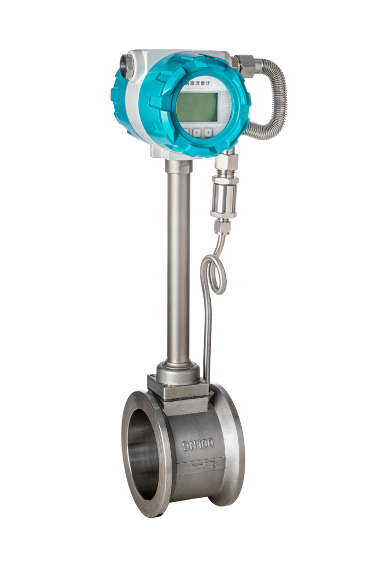
Vortex flow meters are widely used for measuring the flow rate of steam in industrial systems due to their robustness, minimal moving parts, and ability to handle high temperatures and pressures. However, improper installation can lead to significant measurement errors, vibration issues, or even premature instrument failure. This guide outlines the best practices for installing a vortex flow meter in steam lines to ensure long-term accuracy and reliability.
✅ 1. Understand the Measurement Principle
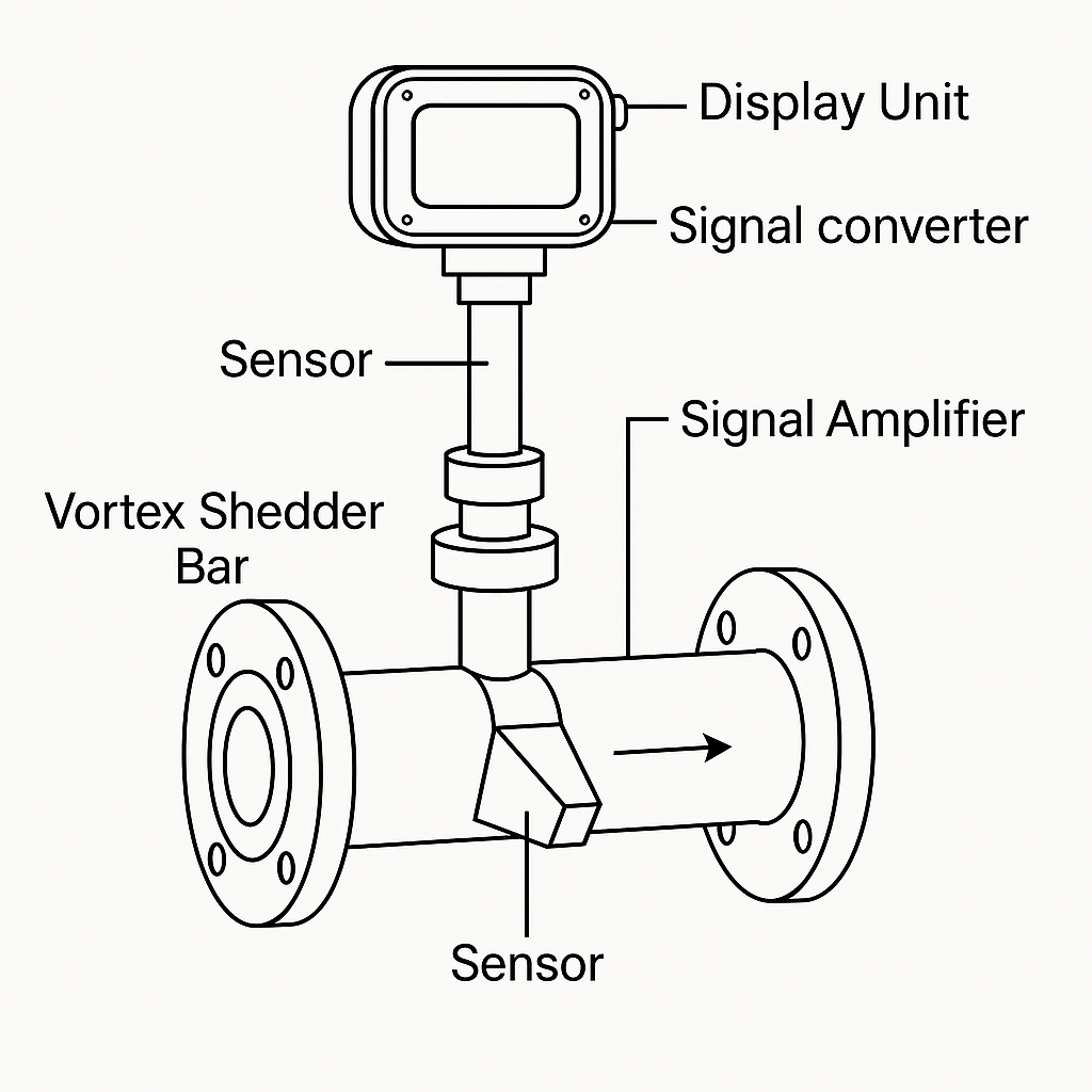
A vortex flow meter operates on the principle of Kármán vortex street. As steam flows past a bluff body in the meter, alternating vortices are shed downstream. The frequency of these vortices is proportional to the flow velocity and is detected by a piezoelectric or ultrasonic sensor.
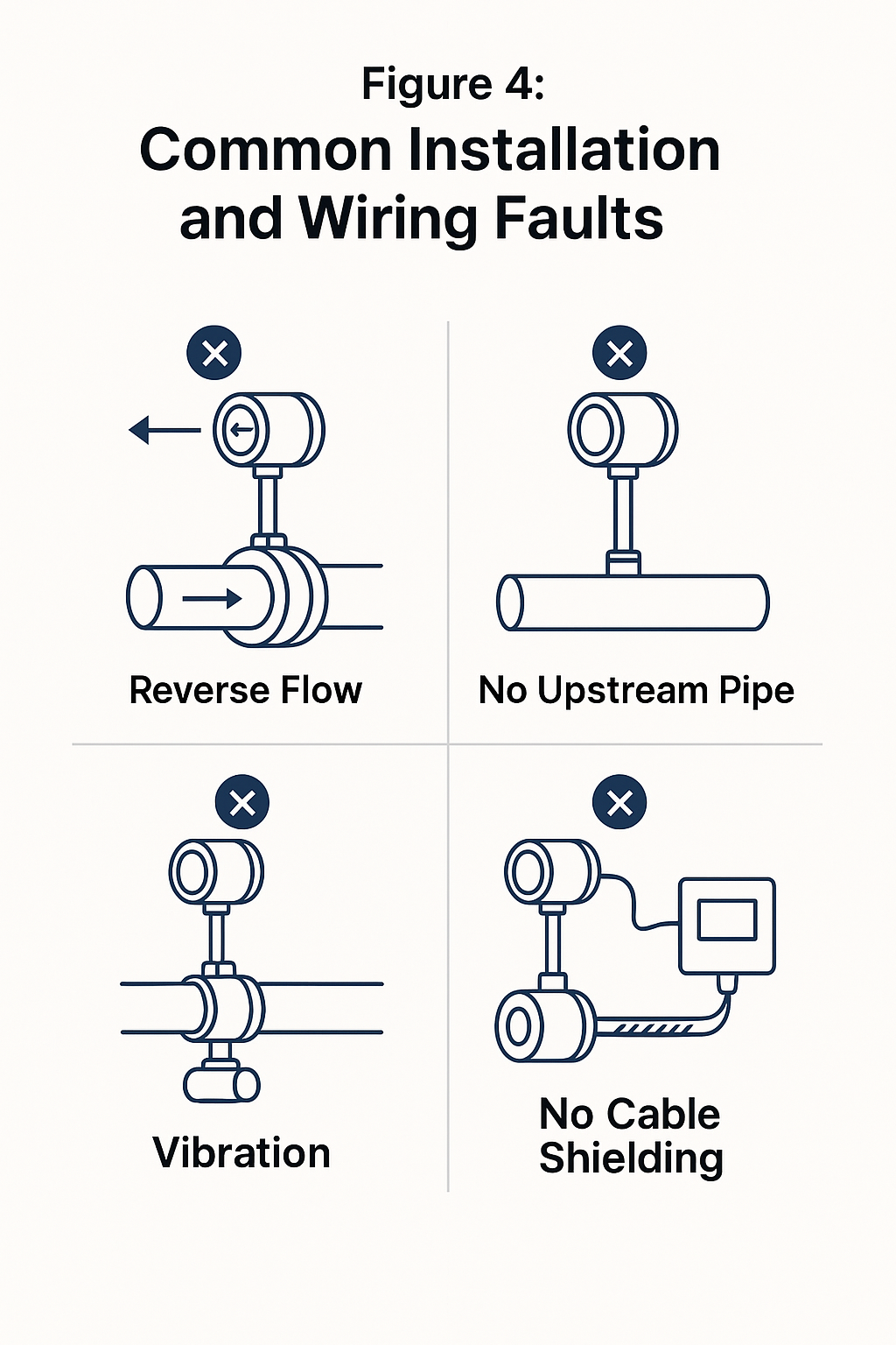
❗ If the flow is unstable or disturbed (due to bends or valves upstream), the vortex shedding will be irregular, resulting in inaccurate readings.
🛠️ 2. Follow Proper Straight Pipe Requirements
One of the most critical installation conditions is ensuring sufficient straight pipe length upstream and downstream of the vortex meter.
Element Type
Minimum Upstream
Minimum Downstream
Single 90° elbow
≥ 15 × DN
≥ 5 × DN
Double elbow (in-plane or out-of-plane)
≥ 20 × DN
≥ 5 × DN
Pump, control valve, reducer
≥ 25 × DN
≥ 5 × DN
DN = Nominal Diameter of the pipe ✅ Install flow straighteners if adequate straight length is not available.
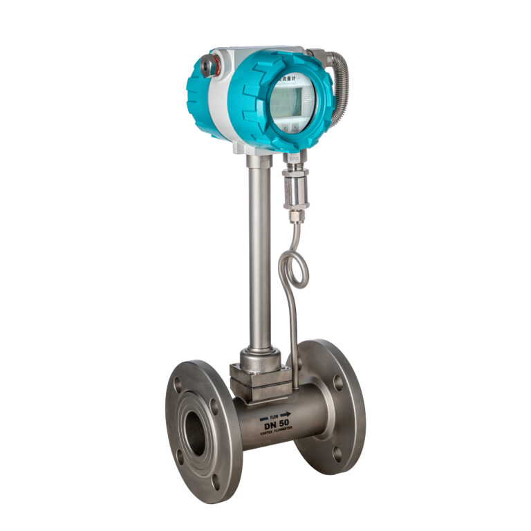
🔄 3. Orientation and Mounting Position
Horizontal Installation (Recommended):
Ensure the vortex meter body is level.
The sensor should be installed vertically upwards to avoid condensate accumulation.
Flow direction must match the arrow on the meter housing.
Vertical Installation:
Only allow upward flow of steam (not downward), to avoid air pocket formation and poor vortex generation.
Avoid installing in locations where condensate might pool (install a drip leg and steam trap upstream).
🌡️ 4. Temperature and Pressure Considerations
Choose a vortex meter rated for saturated or superheated steam temperatures (typically 150–400°C).
Ensure pressure ratings match system operating conditions (e.g., Class 150, 300, or PN25).
🔧 Use gaskets and flanges rated for both high temperature and high pressure.
⚡ 5. Wiring and Signal Output
Use shielded twisted-pair cables for 4–20 mA or pulse signal output.
For Modbus or HART communication, maintain proper grounding and avoid EMI sources.
Always refer to the manufacturer’s wiring diagram before connecting to the control system.
🧪 6. Steam Conditioning and Moisture Management
Install steam traps and strainers before the meter to remove condensate and debris.
Consider adding a separator if the steam quality is low.
Install a bypass line if zero flow measurement or inline maintenance is necessary.
📐 7. Installation Diagram Example
Steam Flow ➝ 25×DN Straight Pipe ➝ Drip Leg & Trap ➝ Flange ➝ Vortex Flow Meter ➝ 5×DN ➝ Process Line
🔎 8. Final Checks and Commissioning
Verify flow direction.
Check for any leaks at flanged connections.
Confirm signal output at zero and full flow.
Calibrate or verify using known flow conditions, if possible.
📌 Conclusion
Correct installation of a vortex flow meter on steam lines is essential for accurate and reliable performance. By following proper straight-run requirements, mounting orientations, and steam conditioning practices, you can avoid common installation pitfalls and ensure optimal measurement accuracy.