For automation engineers, terms like active, passive, powered, and non-powered are commonly encountered. However, many still struggle to clearly differentiate and relate these concepts. This article explains the relationship between transmitter types (active/passive) and DCS I/O card power configurations (powered/non-powered), using a real-world example of the XP351 8-channel AI module.

1. Core Concepts
Active vs Passive Transmitters
Passive Transmitter: Does not have an internal power supply and requires external excitation.
Active Transmitter: Equipped with its own internal power source, capable of supplying output current independently.
Powered vs Non-Powered I/O Cards
Powered Module: Provides a 24V DC supply to external devices (e.g., passive transmitters).
Non-Powered Module: Does not supply voltage to the field; designed to receive signals from active transmitters.
🔄 Mapping Relationship
Powered I/O Module ↔ Passive Transmitter
Non-Powered I/O Module ↔ Active Transmitter

2. Case Study: XP351 AI Module
The XP351 module (by SUPCON) features 8 analog input channels, each configurable via jumper settings:
Jumpers JP1 to JP8 correspond to CH1 to CH8 respectively.
Each jumper controls whether its corresponding channel is powered or non-powered.
| Jumper Position | Mode | DCS Module Behavior | Expected Transmitter Type |
|---|---|---|---|
| Pins 1–2 | Powered | Provides 24V DC | Passive (no internal power) |
| Pins 2–3 | Non-Powered | No power output | Active (has internal power) |
Terminology Note:
Passive Sensor = requires loop power → used with powered module.
Active Sensor = self-powered → used with non-powered module.

3. Wiring Considerations
The polarity of wiring terminals on the I/O module changes based on the power configuration:
For powered channels, the module supplies power, and the transmitter loop connects accordingly.
For non-powered channels, power comes from the transmitter itself, and the module only receives the signal.
Improper jumper settings or incorrect polarity during wiring can result in:
Signal loss
Equipment damage
Erroneous readings
⚠ Always verify jumper settings and terminal polarity before connecting field instruments.

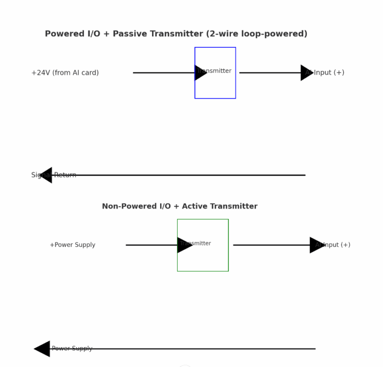
4. Recommended Wiring Diagrams
A. Powered I/O + Passive Transmitter (2-wire loop-powered)
+24V (from AI card) -----> + Transmitter -
                             |
                             |
Signal Return  <----------- - AI Input
B. Non-Powered I/O + Active Transmitter
+ Transmitter -----> + External Power
                      |
                      |
- Transmitter --------> AI Input (Signal)
📌 For 4-20mA loops, ensure proper current flow direction and that total loop resistance is within allowable range.

5. Summary
| Transmitter Type | DCS Card Mode | Jumper Setting | Power Source | Typical Use Case |
|---|---|---|---|---|
| Passive (2-wire) | Powered | JPx: 1–2 | From DCS card | Most field sensors |
| Active (3/4-wire) | Non-Powered | JPx: 2–3 | Internal/External | Advanced transmitters with diagnostics |
Understanding this mapping is essential for proper installation and commissioning of instrumentation systems. Misunderstanding jumper settings may lead to field malfunctions or commissioning delays.
