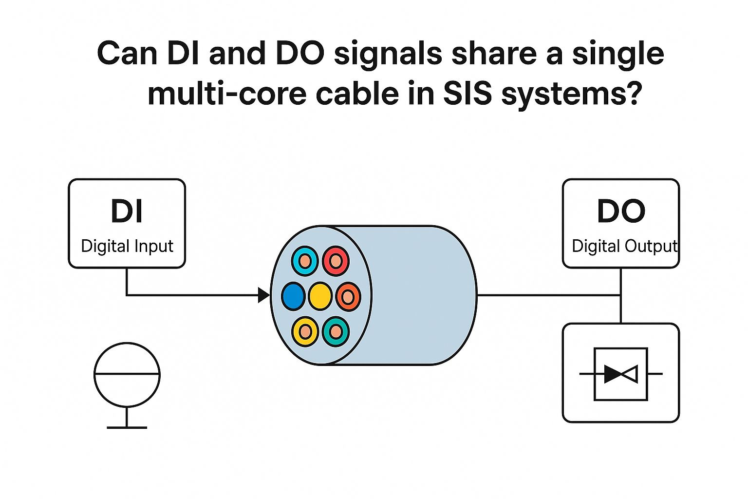
No – It is not recommended to run DI (Digital Input) and DO (Digital Output) signals through the same multi-core cable in a Safety Instrumented System (SIS).
✅ Key Reasons:
Signal Interference Risk
DO signals often drive inductive loads such as relays or contactors, which can generate electromagnetic interference (EMI) or back-emf.
DI signals are typically low-level logic inputs and highly sensitive to crosstalk, which may result in false triggers or spurious alarms.
Troubleshooting and Isolation Challenges
Shared cables make it difficult to independently troubleshoot inputs and outputs.
A single cable fault could affect both DI and DO channels simultaneously.
Violation of Functional Safety Design Principles
SIS design standards (especially for SIL 2 and above) emphasize signal segregation and channel independence.
Combining DI and DO in one cable compromises these safety and reliability requirements.
⚠️ If Combined Cabling is Unavoidable (Not Recommended):
Consideration
Minimum Requirement
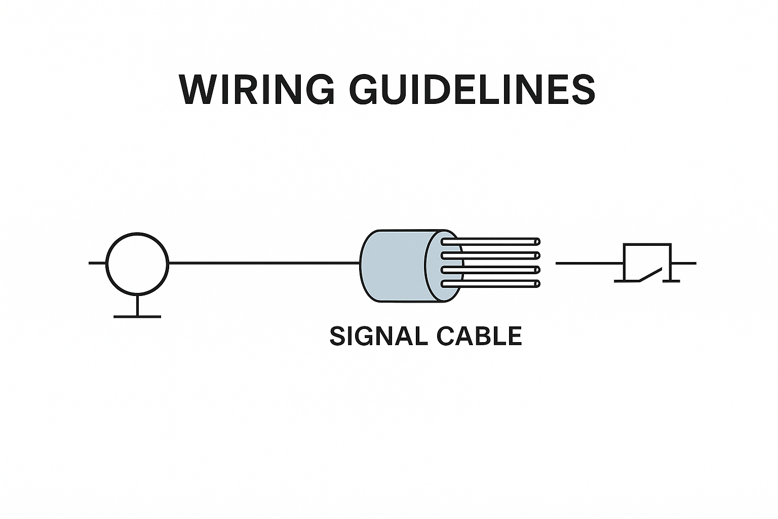
Cable Type
Individually shielded twisted pairs within a shielded multi-core cable
Shielding
Ground shield at both ends (low impedance)
Wire Separation
Physical spacing and clear labeling between DI and DO wires
Usage Limitation
Only allowed in non-SIL-related or low-criticality circuits
✅ Best Practice Recommendations:
Signal Type
Recommended Wiring Practice
DI Signals
Use separate shielded cables or twisted pairs
DO Signals
Route separately; use RC snubber circuits for inductive loads
Power Cables
Never route together with signal cables; maintain ≥15cm physical separation or metal conduit
📝 Conclusion:
In SIS applications, DI and DO signals should be routed via separate cables to ensure electromagnetic compatibility, improve fault isolation, and comply with safety integrity level (SIL) design practices.
If needed, I can also provide a wiring diagram or a bilingual (EN+CN) summary sheet for your team or customer. Let me know if you’d like that.