In process industries such as chemical, pharmaceutical, petrochemical, and food processing, accurate documentation of system design is crucial. Among the most essential engineering drawings are the Process Flow Diagram (PFD) and the Piping and Instrumentation Diagram (P&ID). These diagrams help engineers and operators understand the process flow, equipment layout, and control logic of a plant.
2. What is a Process Flow Diagram (PFD)?
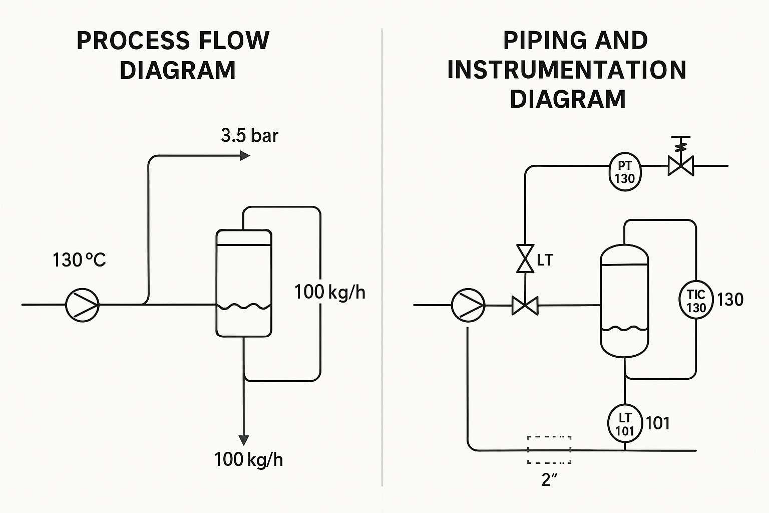
A Process Flow Diagram (PFD) provides a graphical representation of the major steps involved in a chemical or industrial process. It focuses on the high-level flow of materials and energy within a facility, showing major equipment, basic piping, and key control valves.
Key Features:
Displays main process routes and equipment
Shows mass and energy balances
Includes basic control elements
Omits minor piping details
Typical Components:
Pumps, compressors, reactors, heat exchangers
Major pipelines and flow directions
Temperature, pressure, and flow rate data
Control valves and process control loops (simplified)
3. What is a Piping and Instrumentation Diagram (P&ID)?
A Piping and Instrumentation Diagram (P&ID) provides a more detailed illustration than a PFD. It includes all process piping, instrumentation, control devices, insulation, and safety components. It is used in detailed design, installation, commissioning, and maintenance phases.
Key Features:
Detailed equipment symbols and tags
All piping lines with sizes and insulation details
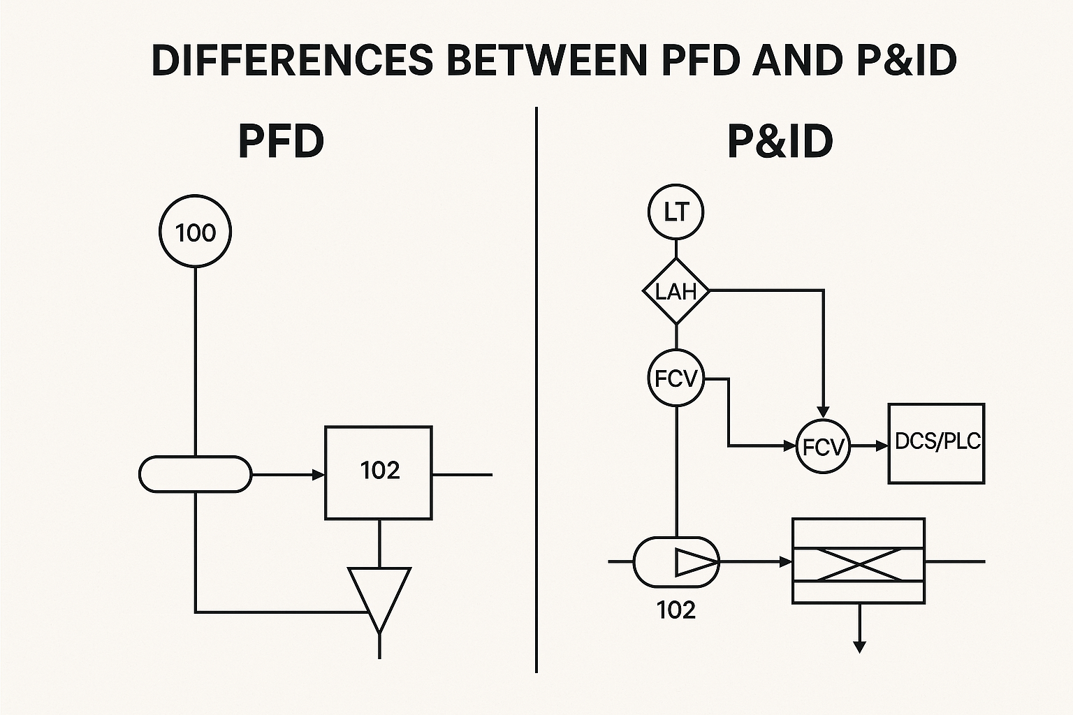
Symbols in both diagrams follow industry standards such as ISO, ANSI, and ISA. Below are examples:
Valves: Gate, globe, control, check
Equipment: Pumps, compressors, tanks, exchangers
Lines:
Solid: Process piping
Dashed: Signal or pneumatic lines
Instruments: Temperature transmitter (TT), pressure indicator (PI), flow control valve (FCV)
6. Standard Guidelines and References
ISO 10628: Flow diagrams for process plants
ISO 14617: Graphical symbols for diagrams
ISA S5.1: Instrumentation symbols and identification
ANSI/ISA-5.4: Instrument loop diagrams
7. Application in Industry
PFDs and P&IDs are critical in:
Engineering design packages
Construction and installation plans
Process optimization and troubleshooting
Regulatory compliance and safety reviews
8. Conclusion
Understanding the distinctions and applications of PFDs and P&IDs is fundamental in industrial process engineering. While PFDs offer a simplified overview of the process, P&IDs provide the granular detail necessary for installation, control, and maintenance. Both diagrams, when correctly developed and used, ensure safe, efficient, and reliable operations in process industries.