1. Introduction Pressure gauges play a critical role in monitoring process pressure across industrial systems. Ensuring their safe and accurate performance is vital for operator safety, equipment protection, and process stability. This document outlines key safety measures including overpressure protection, environmental considerations, and vibration resistance for pressure gauges.
2. Overpressure and Pressure Relief Protection
2.1 Normal Operating Range Pressure gauges are recommended to operate within 30% to 70% of their full-scale range. Fluctuating process pressures that exceed this range can damage the sensing element and cause rupture.
2.2 Pressure Relief Devices According to GB/T 1226:
For gas media ≥2.5 MPa and liquid media ≥6 MPa, a pressure relief plug is required.
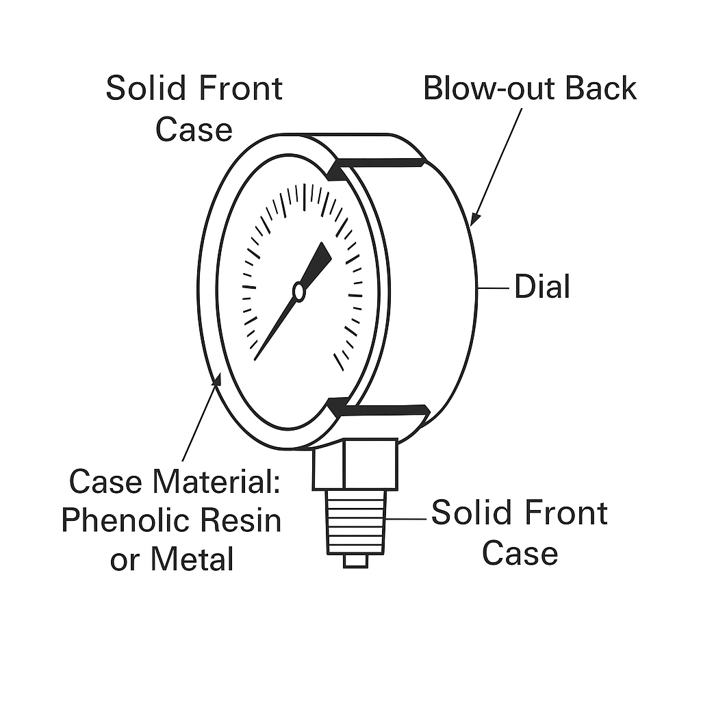
For critical applications, use a solid front case with a blow-out back to protect operators.
Table 1. Relief Device Requirements
Medium Type
Pressure Threshold
Relief Device Required
Gas
≥2.89 MPa (400 psi)
Yes
Liquid
≥6.9 MPa (1000 psi)
Yes
Figure 1. Solid Front Case Pressure Gauge
2.3 Overpressure Protection
Bourdon tube gauges: withstand up to 130% of full-scale pressure.
Diaphragm/bellows gauges: may include mechanical stops to tolerate up to 10x full scale.
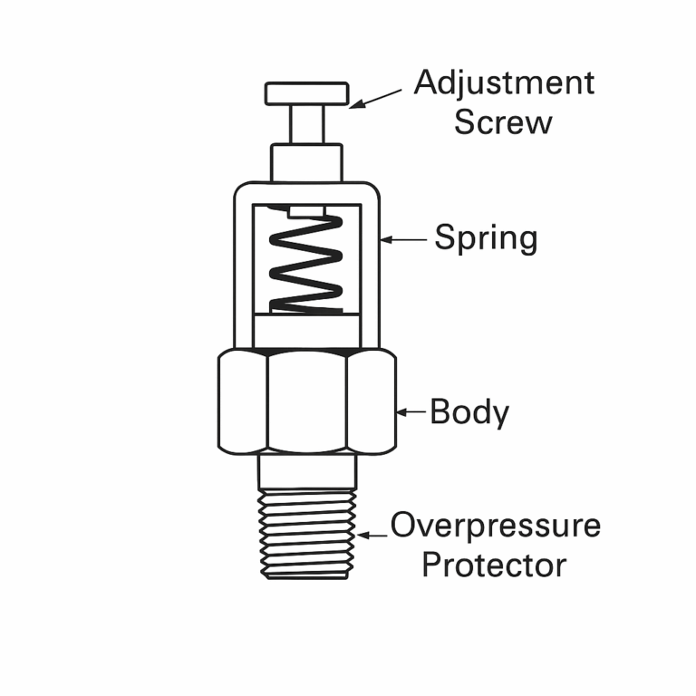
For high-risk applications, add an external overpressure protector (e.g., ASME B40.100 Part 5).
Figure 2. Overpressure Protector Valve Design
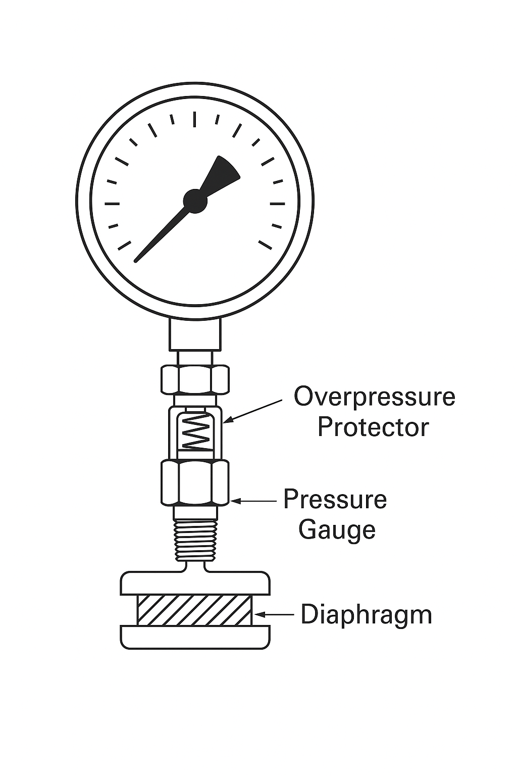
Figure 3. Diaphragm Gauge with Overpressure Protection
3. Environmental Temperature Considerations
3.1 Ambient Temperature Typical operating temperature ranges:
Table 2. Recommended Operating Temperature Ranges
Gauge Type
Temperature Range (°C)
Standard Dry Gauge
-40 to 70
Liquid-Filled Gauge
5 to 40
Solid Front Case
-25 to 55
Electrical Contact Gauge
-40 to 60
Temperature variations can cause internal pressure changes in sealed gauges (IP65+), leading to reading errors. Venting plugs or breathable diaphragms are used for compensation.
3.2 Low Temperature Effects
May cause fogging of the lens or condensation inside the case.
Use breathable vents or choose glycerin/silicone-filled vibration-resistant gauges.
4. Media Temperature Impact
Ideal media temperature: below 60°C.
High temperature can distort readings and degrade soldered parts in brass internals.
Protection Methods:
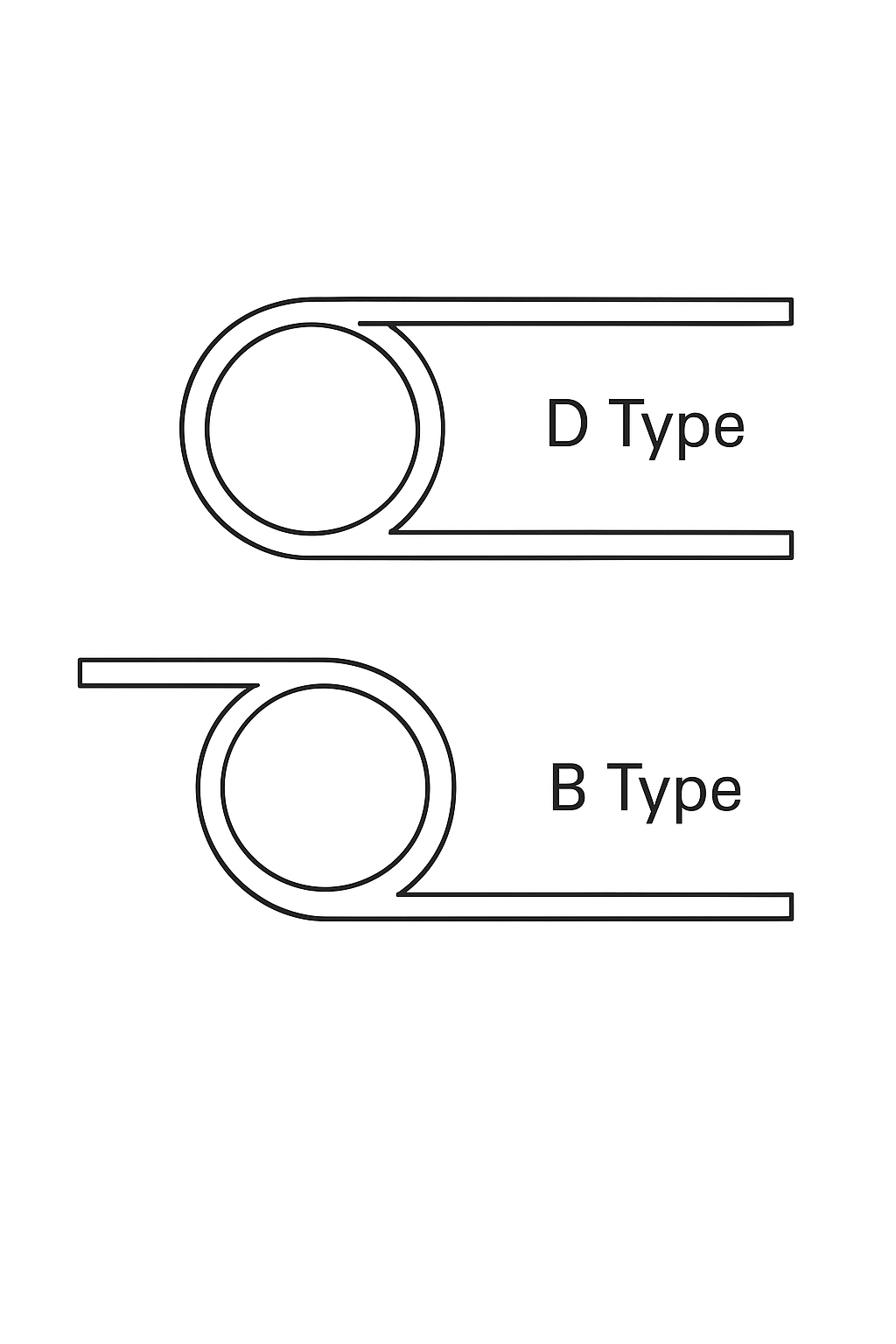
Use cooling elements (e.g., siphons or cooling coils):
D-type siphon for horizontal pipes.
B-type for vertical installations.
Figure 4. Cooling Coil Types (DIN 16282)
For temperatures >150°C: Use diaphragm seals.
For >300°C: Add a heat-dissipating adapter or capillary tubing between gauge and diaphragm.
5. Vibration Resistance Measures
5.1 Site Conditions
Comply with GB/T 17214.3 VH3 vibration limits.
5.2 Anti-Vibration Gauge Design
Use liquid-filled cases (e.g., glycerin, silicone, or fluorinated oil).
Match fill fluid with process temperature and compatibility.
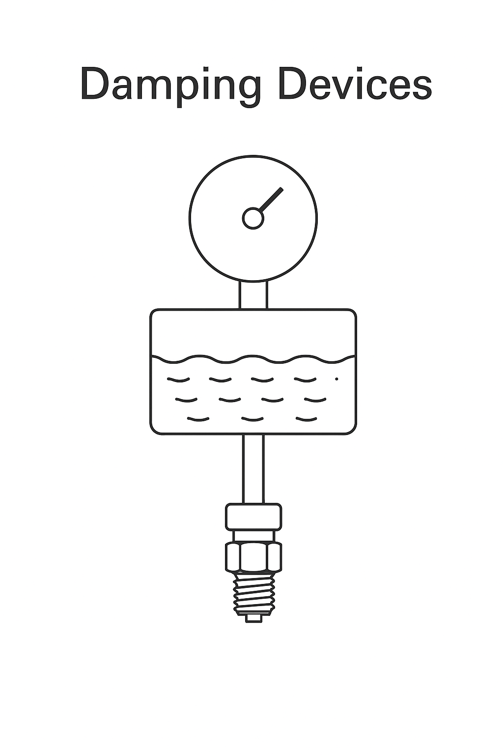
5.3 Damping Devices
Add damping screws or external restrictors to suppress signal pulsation.
Figure 5. Damping Device Installations
6. Conclusion Safe pressure gauge usage requires systematic consideration of overpressure risks, temperature influences, and environmental vibrations. By selecting appropriate components and protection mechanisms, users can ensure measurement reliability and prevent hazardous incidents.
Appendix: Standards Referenced
GB/T 1226: General Purpose Pressure Gauges
GB/T 17214.3: Working Conditions for Process Measurement Equipment
ASME B40.100: Pressure Gauge Specifications
EN 837-2: Bourdon Tube Pressure Gauge Safety Requirements