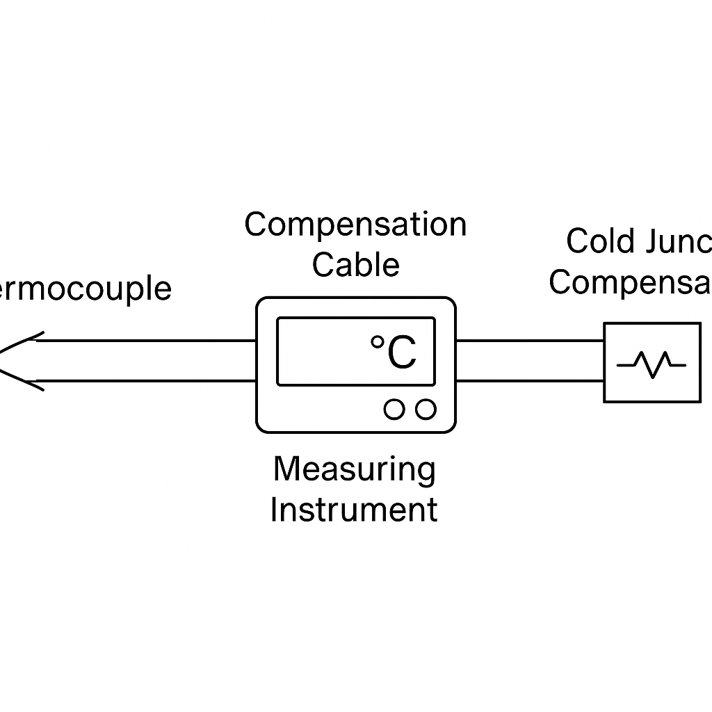
Compensation cables are specially designed wires used in temperature measurement systems to compensate for ambient temperature variations at the cold junction (reference junction) of thermocouples. They play a vital role in maintaining the accuracy of temperature signals over long distances.
1. Core Functions
🔹 Cold Junction Compensation
When the cold junction of a thermocouple is located far from the measuring instrument, compensation cables extend the signal transmission path while minimizing errors caused by ambient temperature changes at the reference point.
🔹 Matching Thermoelectric Properties
These cables are made of alloys with thermoelectric properties that closely match those of the corresponding thermocouple types within a low-temperature range (typically 0–200°C), ensuring accurate signal transmission.
2. Working Principle
Compensation cables simulate the thermoelectric characteristics of thermocouples in low-temperature zones by using specific materials (e.g., nickel-chromium, copper-nickel alloys). This offsets any thermal EMF deviation caused by temperature differences at the cold junction.
3. Types of Compensation Cables
Type
Suffix
Material
Features
Application Scenario
Extension
X
Same as thermocouple
High accuracy, higher cost
Precision temperature control
Compensation
C
Similar but not identical
Economical, widely applicable
General industrial environments
Example: K-type thermocouples can use KX (extension) or KC (compensation) cables depending on accuracy and cost considerations.
4. Structural Features
Insulation and Sheath Materials: Common options include PVC, PTFE, or glass fiber, selected based on temperature resistance and environment.
Shielding: Braided copper or foil shielding improves resistance to electromagnetic interference in complex industrial environments.
Color Coding: Standardized to help identify thermocouple types and polarity.
5. Selection Guidelines
Criterion
Recommendation
Thermocouple Type
Must match exactly (e.g., K-type uses KX or KC cable)
Petrochemical Pipelines: Corrosion-resistant designs are preferred.
Laboratory Systems: Use extension-grade cables for high-precision measurement.
7. Common Issues & Mistakes
Issue
Description
Reversed Polarity
Connecting the wires with incorrect polarity may double the cold junction error. Always follow color codes and polarity markings.
Exceeding Temperature Limits
Compensation cables are only effective within rated temperature ranges. For high-temperature zones, use actual thermocouple wire.
Type Mismatch
Using KC cable with a J-type thermocouple, for example, will introduce significant error.
8. Example Use Case
In a plastic extrusion temperature control system, a K-type thermocouple paired with a KC compensation cable is used to extend the cold junction into a control cabinet where the temperature is stable. With additional cold-junction compensation circuitry inside the cabinet, the system achieves a temperature control precision within ±1°C.
❗Note: Improper cable selection in such systems may result in an additional error of 2–5°C, which is critical in precision temperature control.
✅ Conclusion
Thermocouple compensation cables may appear simple, but they play a decisive role in the overall accuracy and reliability of temperature measurement systems. Choosing the correct cable type, structure, and installation method is essential for ensuring optimal system performance in industrial and laboratory settings.