In modern machine tools, multiple motors and components often work together to achieve complex mechanical tasks. To ensure operational safety and meet process requirements, these motors and components must follow a predefined sequence and interact with one another. This coordination is achieved through electrical interlocking systems.
This article introduces the most commonly used interlocking methods in machine tool electrical systems, including multi-point control, mutual interlocking, condition-based interlocking, self-holding circuits, and sequential control.
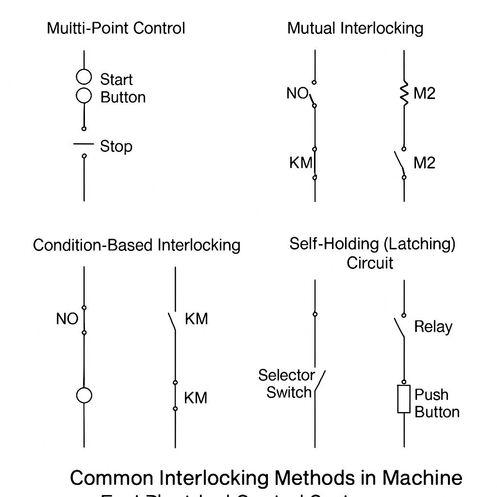
1. Multi-Point Control
For large-scale machines or when required by the working environment, multiple control stations may be needed. Each station is equipped with a set of control buttons.
Wiring Principle:
All start buttons (NO contacts) are connected in parallel.
All stop buttons (NC contacts) are connected in series.
This setup ensures that the machine can be started from any station and stopped from any station as well.
2. Interlocking Control
To ensure safety and proper workflow, certain components must operate in a specific sequence or not operate simultaneously. Interlocking prevents potential accidents and ensures process compliance. There are three major types:
2.1 Mutual Interlocking
When two or more components must not operate simultaneously to avoid hazards, mutual interlocking is applied.
Typical Applications: Forward/reverse motor control, moving and clamping mechanisms, primary and auxiliary drive systems.
Wiring Principle: The normally closed (NC) contact of one contactor is inserted into the control loop of the other, ensuring only one can be energized at a time.
2.2 Condition-Based Interlocking (Prerequisite Interlock)
This method ensures that a specific component only operates when a precondition is met.
Examples:
The worktable feed only starts after the spindle is running.
Other components only activate after the lubrication system is functioning.
Wiring Principle: The normally open (NO) contact of the condition device is connected in series with the control coil of the dependent device.
2.3 Self-Holding (Latching) Circuit
Widely used in jog and continuous operation control modes of machine tools.
Implementation Methods:
Selector switch control
Dual-function push buttons
Relay-based holding circuits
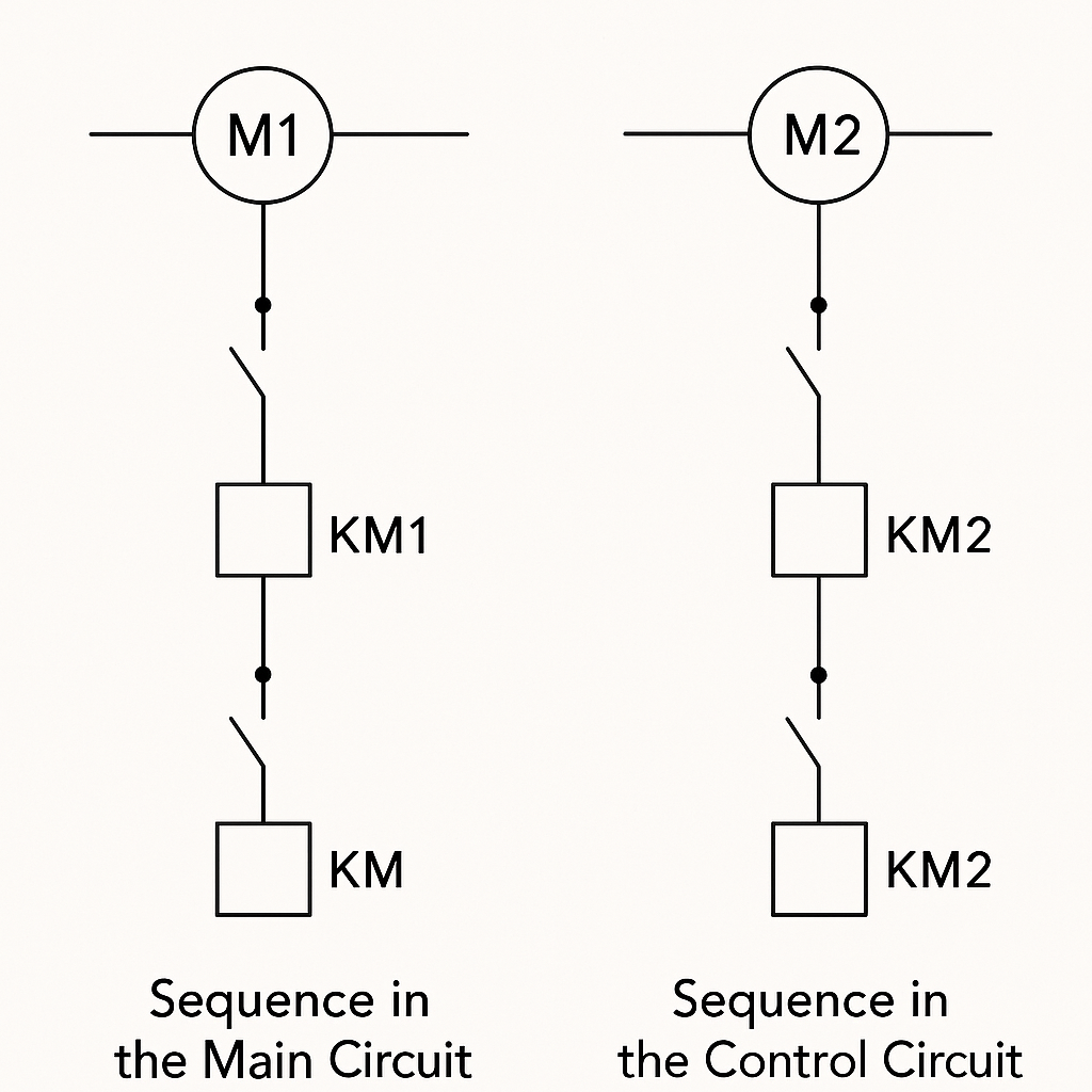
3. Sequential Control
When the operation sequence of motors or devices must strictly follow the process flow, sequential control is applied.
3.1 Sequence in the Main Circuit
Wiring Principle: The auxiliary contact of one motor’s contactor is connected after another’s, enforcing a startup order.
Use Case: Motor M2 cannot start until M1 has started.
3.2 Sequence in the Control Circuit
Wiring Principle: The NO auxiliary contact of the first motor’s contactor (e.g., KM1) is placed in series with the control circuit of the next motor (e.g., KM2).
This ensures strict adherence to the required startup or shutdown sequence.
Conclusion
Electrical interlocking is a fundamental design concept in machine tool control systems. Whether for safety, efficiency, or process compliance, proper application of interlocking logic significantly reduces operational risk and enhances automation performance. Understanding and implementing various interlocking methods is essential for engineers, technicians, and machine tool integrators.