In chemical plants and industrial facilities, the presence of flammable and toxic gases is a common hazard due to process leaks, equipment failures, or accidental releases. To ensure personnel safety and prevent fire or explosion incidents, it is essential to install Gas Detection and Alarm Systems (GDS) at locations where such gases are likely to leak or accumulate.
A critical engineering question often arises:
Can a Distributed Control System (DCS) be used as the main controller for a GDS?
The short answer is: not directly. This article explains why.

1. Overview of GDS Architecture
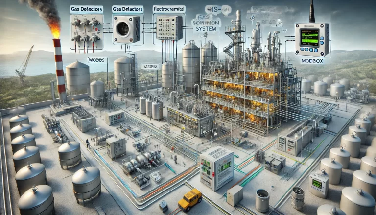
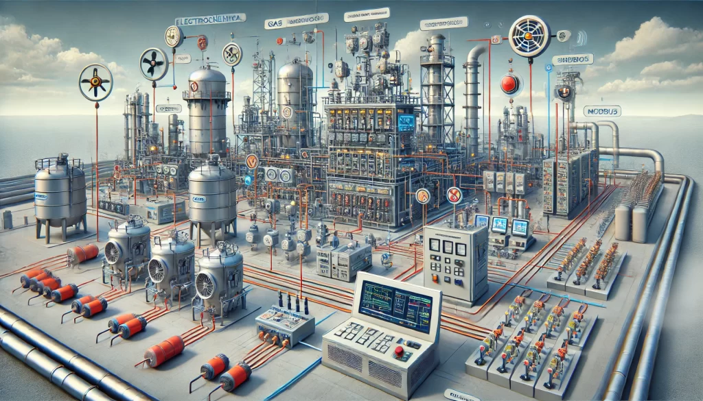
A complete gas detection system typically includes:
Gas detectors/sensors (electrochemical, infrared, catalytic bead, etc.)
Alarm control panels or GDS controllers
Signal transmission to the central control room (via 4–20mA, Modbus RTU, etc.)
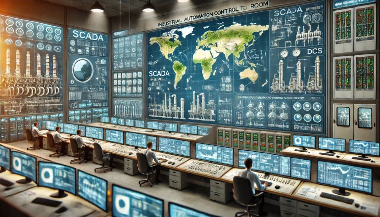
Display/processing system, often integrated into a DCS or SCADA for visualization
Alarm and emergency interlock outputs, such as triggering ventilation, stopping pumps, or initiating shutdowns

2. The Role of a DCS in Gas Detection
While a DCS can integrate with GDS to perform display, trend analysis, and even logic interlocks, it is not designed to replace a dedicated GDS controller. Here’s how a DCS contributes to GDS operations:
✅ What a DCS Can Do:
Acquire sensor signals (analog 4–20 mA or digital via Modbus)
Display gas concentrations on HMI/SCADA
Trigger interlocks or process shutdowns upon alarm conditions
Log alarms and events for future diagnostics and audit
Generate maintenance reminders and trend evaluations
❌ What a DCS Cannot Do Reliably:
| Function | Limitation |
|---|---|
| Safety-critical decision-making | Most DCS platforms are not SIL-rated (Safety Integrity Level), while GDS controllers must meet SIL2 or SIL3 requirements. |
| Explosion protection | DCS components may not be certified for hazardous environments (e.g., ATEX, IECEx), whereas GDS controllers often are. |
| Dedicated alarm management | Specialized GDS controllers provide independent visual/audio alarms even if the DCS fails. |
| Redundancy and reliability | GDS controllers typically have built-in redundancy, power fail-safe designs, and local diagnostics that a general-purpose DCS may lack. |

3. Recommended Integration Strategy
The industry’s best practice is to treat GDS and DCS as complementary systems:
| Component | Responsibility |
|---|---|
| GDS Controller | Acts as the primary safety layer. Independently processes sensor signals, generates alarms, and initiates emergency shutdowns. |
| DCS System | Receives GDS signals for operator visualization, process interlock execution, and historical logging. Acts as the monitoring layer, not the safety core. |
| Safety Instrumented System (SIS) | In high-risk applications, a separate SIS (with certified safety PLCs) should be used for executing safety shutdowns initiated by GDS alarms. |
4. Case Study: Refinery Gas Detection Design
In a major refinery project, flammable gas detectors from a third-party manufacturer (e.g., MSA, Dräger) were connected to a dedicated GDS panel with redundant CPUs and explosion-proof housing.
The GDS panel output both:
Analog and digital signals to the DCS for display and trends
Hardwired contacts to the SIS/ESD system for triggering ventilation and shutdown actions
This ensured full compliance with safety codes, and DCS served only a monitoring and control support role.

5. Final Recommendation
While DCS systems offer great flexibility for monitoring and process control, they should not be used as the sole controller for critical safety functions like gas detection.
To ensure safe and compliant operations:
Use dedicated, certified GDS controllers for gas detection and alarm logic
Use DCS as a visualization and process integration platform
Interface with SIS/ESD systems for critical alarm handling and emergency shutdowns
