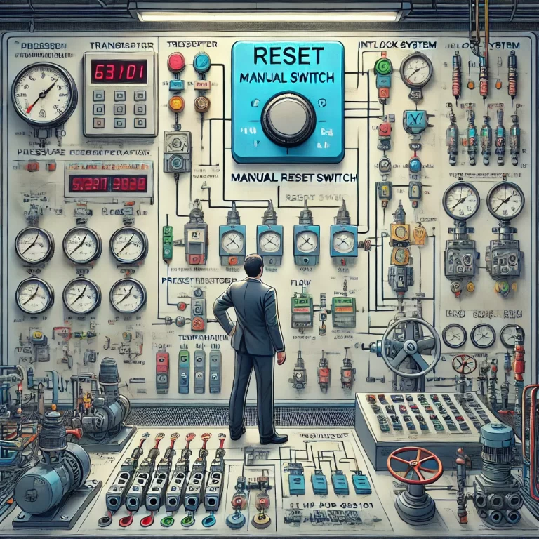
In the field of industrial automation, interlock logic diagrams act as the “safety brain” of a system—precisely controlling equipment startup/shutdown, alarm responses, and emergency shutdown sequences. They are directly tied to personnel safety and the stable operation of multimillion-dollar facilities.
An improperly designed reset switch can render interlock protection ineffective. Even worse, a small error in the logic diagram could cause a cascading production accident. This article walks you through the design principles of reset switches, their implementation in interlock systems, and the use of RS flip-flops for safe and effective logic control.
1. Why Is a Reset Switch Necessary?
In industrial control systems, when critical process parameters—such as pressure, temperature, or flow—exceed safety thresholds, the interlock protection mechanism is triggered automatically. This action places the system into a safe state by shutting down pumps, closing valves, or stopping machinery.
❗ Problem Without Reset Logic:
If process parameters fluctuate and return to normal automatically, and the system is configured to reset itself without inspection, it may resume operation before confirming root causes, leading to repeated trips and unstable production.
✅ Role of the Reset Switch:
To prevent this, a manual reset switch is used. Once the process returns to normal, operators must inspect the system and manually trigger the reset, ensuring that conditions are truly safe before restoring operation.
This approach prevents unwanted cycling of interlocks and ensures safe, controlled recovery after process upsets.

2. Design Requirements for Reset Switches
Reset switches can be implemented as soft switches in the DCS (Distributed Control System), or—when interlocks are handled by the SIS (Safety Instrumented System)—can communicate signals between DCS and SIS.
🛠 Common Reset Configurations:
Soft Switch in SIS HMI: Displayed as a greyed-out button unless allowed.
Enabling Switch on Auxiliary Panel: The reset command is only valid when this switch is in the “Enable” position.
Two-Stage Verification: Reset is accepted only after all interlock conditions have returned to normal.
⚠ Reset Switch Only Resets Actuated Devices:
It is important to note that the reset function only clears the actuator state (e.g., valve, pump) after the triggering parameter is no longer in alarm. If process parameters are still abnormal, the system will not allow reset.
3. Logic Implementation Using RS Flip-Flops
Reset switches are typically used in conjunction with RS flip-flops in logic diagrams. Understanding RS flip-flop behavior is critical for correct implementation.
3.1 Set-Priority RS Flip-Flop (Figure 1)
| Input A (S) | Input B (R) | Output C (Q) | Behavior |
|---|---|---|---|
| 1 | 0 | 1 | Set |
| 0 | 1 | 0 | Reset |
| 1 | 1 | 1 | Set priority |
| 0 | 0 | Hold last state | — |
3.2 Reset-Priority RS Flip-Flop (Figure 2)
| Input A (S) | Input B (R) | Output C (Q) | Behavior |
|---|---|---|---|
| 1 | 0 | 1 | Set |
| 0 | 1 | 0 | Reset |
| 1 | 1 | 0 | Reset priority |
| 0 | 0 | Hold last state | — |
4. Application Example: Interlock for a Valve Control
Refer to Figure 3 for the logic diagram involving a pressure transmitter PZT-63101 and a valve XV-63101. The interlock is triggered when PZT-63101 ≥ 0.3 MPa.
Logic Description:
The interlock triggers when the pressure rises.
The signal is inverted before entering the “Set” (S) terminal of the RS flip-flop.
The flip-flop outputs a signal to close
XV-63101.
When pressure returns below 0.3 MPa:
The Set input returns to “0”.
The RS flip-flop holds its output until a manual reset is issued.
Once the operator confirms safety and presses the reset switch, the Reset (R) input is set to “1”, reopening
XV-63101.
⚠ If a reset-priority flip-flop is used here, the system may prematurely reset while the alarm condition still exists—a safety hazard. Thus, a set-priority flip-flop is preferred in most interlock logic.

5. Handling Multiple Interlock Conditions
Sometimes multiple interlock logics affect the same output device (e.g., a valve), but with different triggering conditions.
Potential Risk:
One interlock is cleared while another is still active.
An operator resets the system prematurely, causing unsafe equipment activation.
Recommended Solutions:
Unified Reset Design: Use a common reset switch for all related interlocks.
AND Gate Logic on Output: When multiple interlocks control one device, insert an AND gate. Only when all interlocks are cleared, the final output allows the device to resume operation.
6. Final Recommendations
Reset switch design is often undervalued because it lies on the periphery of the logic diagram. However, an incorrectly designed reset circuit can compromise the entire safety integrity of the system.
✅ Best Practice:
Ensure close coordination between process engineers and automation engineers.
Clarify all interlock logic relationships.
Choose the appropriate RS flip-flop based on safety requirements.
Implement thorough testing before commissioning.
