1. Overview of Push Buttons
A push button is a type of manual control switch that is actuated by applying pressure using a part of the human body—typically the finger or palm. Equipped with a built-in spring mechanism for resetting, it is one of the most commonly used control devices in industrial and electrical systems.
Push buttons typically operate in control circuits with small currents (generally not exceeding 5A). They do not directly control high-current main circuits. Instead, they send control signals to devices such as contactors or relays, which in turn manage the switching, function conversion, or interlocking of the main circuit.
Typical Applications Include:
Motor start/stop controls
Circuit breaker operations in distribution panels
Automated process control in industrial systems
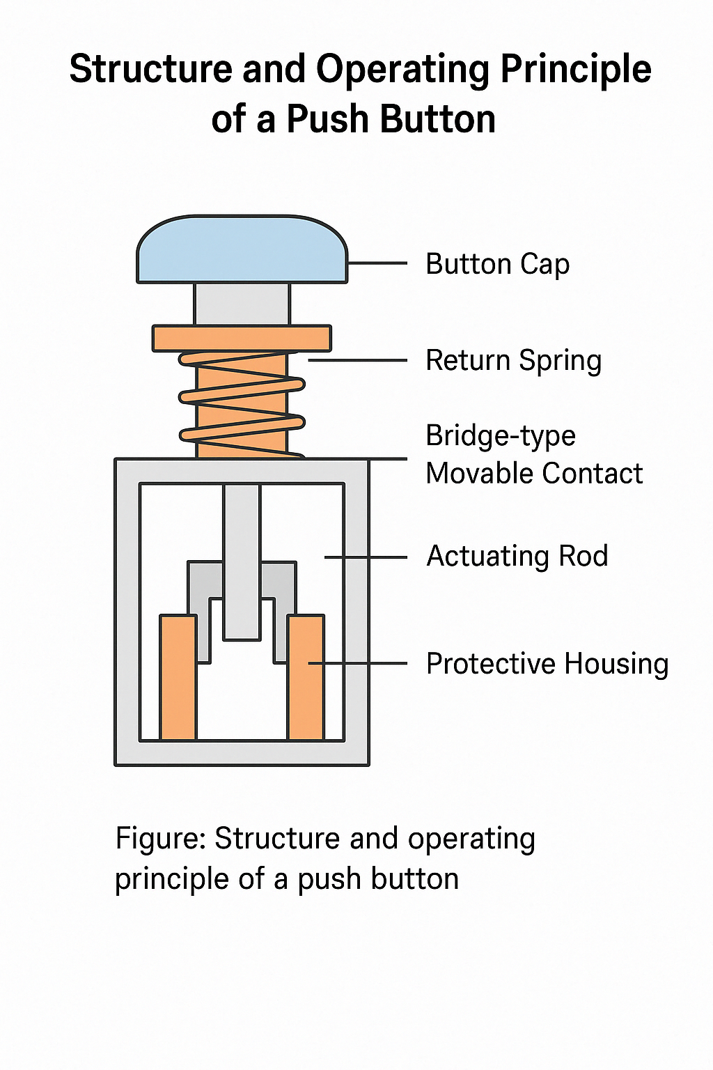
2. Structure and Operating Principle
A typical push button is composed of the following parts:
Button cap
Return spring
Bridge-type movable contact
Fixed contacts
Actuating rod
Protective housing
Contact Types Based on Resting State (No External Force):
Normally Closed (NC) or Stop Button: Opens upon pressing
Normally Open (NO) or Start Button: Closes upon pressing
Composite Button: Combines both NO and NC contacts in one device
When a force is applied, the internal contacts change state, altering the electrical continuity of the circuit.
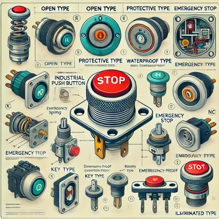
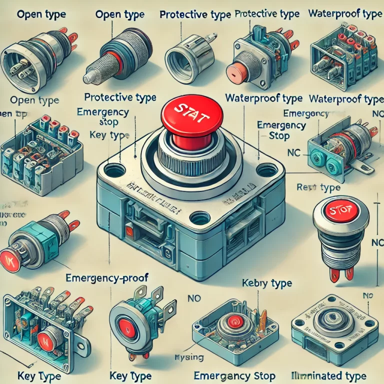
3. Classification of Push Buttons
3.1 Based on Protection and Functionality
| Code | Type | Description & Application |
|---|---|---|
| K | Open Type | No protective shell, suitable for dry indoor panels |
| H | Protective Type | Transparent shield for safety, ideal for factory environments |
| S | Waterproof Type | Sealed against water, suitable for outdoor use |
| J | Emergency Type | Red mushroom-style cap for quick emergency shutdown |
| Y | Key Type | Requires a special key, used in critical systems to avoid misuse |
| F | Corrosion-Proof | Designed to resist chemical corrosion |
| X | Rotary Type | Operated by rotating knob, toggles between ON/OFF |
| D | Illuminated Type | Built-in indicator light for status display |
3.2 Based on Contact Configuration
Single-Contact Button: One NO or NC contact, used for simple control circuits
Dual-Contact (Composite) Button: Contains both NO and NC contacts, supports interlocking or self-hold circuits
Illuminated Button (D-Type): Integrated LED for visual feedback and status monitoring
4. Guidelines for Button Selection
4.1 Functional Requirements
Operation Method:
Frequent operation: Use spring-return type
Status-hold needed: Use latch-type/self-locking design
Indication Need:
Use D-type (illuminated) buttons to show operational status
Safety Considerations:
Emergency stop buttons must be red mushroom heads (J-type) with an actuation force ≥ 2N (as per GB/T 14048.5)
4.2 Environmental Adaptability
Corrosive Environments: Use F-type with corrosion-resistant housing
Wet/Dusty Conditions: Choose products with IP54–IP65 protection rating
Extreme Temperatures:
50°C: Heat-resistant plastics
<-20°C: Avoid plastic that may become brittle
4.3 Electrical Parameters
Current Rating: Typical ≤5A; for larger loads, use relay-assisted switching
Voltage Rating:
AC 380V requires ≥500V-rated buttons
DC systems require polarity-specific designs
Mechanical Durability:
General use: ≥100,000 cycles
Precision systems: ≥500,000 cycles
4.4 Color Code Recommendations
| Button Function | Recommended Color |
|---|---|
| Start | White, Green, or Black (preferably White) |
| Stop | Black, White, or Red (preferably Black) |
| Emergency Stop | Red only |
| Indicator (Status) | Typically Green (RUN) / Red (STOP) |
5. Application Case Study
Scenario: Motor control for a chemical reactor stirring system
Conditions:
Ambient temperature: 45°C
Acidic vapors present
50 daily start/stop cycles
Selection Process:
Protection Needs: Corrosion-proof (F-Type) + IP55 enclosure
Control Requirements: Composite button for self-locking
Safety Feature: Separate red mushroom-type emergency stop button (J-Type)
Electrical Specs: AC 220V, 5A load with a green LED indicator
Final Selection:
LAY1-01 corrosion-resistant composite button
J-Type emergency stop module
D-Type indicator light included
6. Common Failures and Troubleshooting
| Problem | Cause | Solution |
|---|---|---|
| Contact Sticking | Arcing and oxidation on contacts | Polish with fine sandpaper; replace with silver-nickel contacts if worn |
| Frequent Misoperation | Accidental presses or loose installation | Add mechanical interlocks or dual-button activation logic |
| Indicator Light Failure | Burnt-out LED or overvoltage | Replace with low-power LED (<5mA); install limiting resistor |
7. Conclusion
Push buttons, though simple in appearance, are crucial components in industrial control circuits. Their proper selection and maintenance directly impact equipment safety, reliability, and usability. By understanding button classifications, design principles, and environmental considerations, engineers can ensure optimal control system performance across a variety of industrial settings.