1. Fundamental Differences
1.1 Function and Role
| Category | Surge Protective Device (SPD) | Lightning Terminal |
|---|---|---|
| Core Function | Limits transient overvoltages (such as lightning surges or switching transients) on power or signal lines. | Ensures reliable electrical connection between lightning arrestors and grounding system to discharge lightning current safely. |
| Target | Directly protects electronic equipment or control systems from voltage spikes. | Acts as the grounding hub in a lightning protection system, facilitating low-impedance current flow into the earth. |
| Performance Requirements | Fast response (nanosecond scale), high energy dissipation capacity. | Low contact resistance, high conductivity (typically copper), mechanical strength, long-term stability. |
1.2 Structure and Composition
Surge Protective Device (SPD):
Modular & Complex Design: Includes voltage-sensing elements (e.g., MOVs), discharge paths, thermal disconnects, and status indicators.
Form Factor: Power SPDs are often rail-mounted modules; signal SPDs may appear as network, coaxial, or telecom adapters.
Installation: Connected in parallel (or occasionally in series) close to the protected device.
Lightning Terminal:
Simple Mechanical Connectors: Typically copper busbars, bolts, weld terminals; surface-treated (e.g., tin/zinc-plated) for corrosion resistance.
Form Factor: Found at connection points between down conductors and grounding electrodes, or between equipment chassis and grounding busbars.
Installation: Installed using welding, bolting, or exothermic bonding, following mechanical and electrical continuity requirements.
1.3 Application Scenarios
| Device | Application Scenario | Installation Point |
|---|---|---|
| SPD | Protecting electronics (PLCs, servers, surveillance cameras), power systems (distribution panels, UPS), signal systems (network, video, antenna). | Close to protected equipment, typically inside distribution boards or near network interfaces. |
| Lightning Terminal | Key connection points in the grounding system—lightning rods to down conductors, down conductors to ground electrodes, equipment chassis to main grounding grid. | On building exteriors, grounding rooms, control cabinets. Must comply with building lightning protection codes. |
2. Internal Relationship and Cooperation
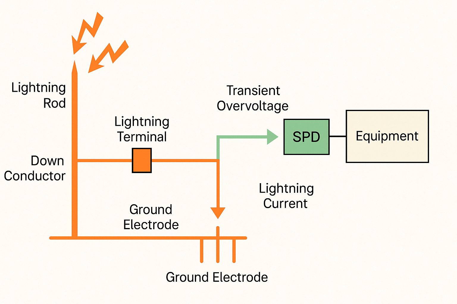
2.1 Synergistic Roles in Lightning Protection Systems
SPD = Precision Protection: Designed to clamp and dissipate transient overvoltages induced by indirect lightning or switching operations.
Lightning Terminal = Grounding Channel: Ensures that lightning current captured by external lightning rods travels safely into the earth via low-impedance paths.
⚠ Note: Poor contact or corrosion at the lightning terminal can increase grounding resistance, which in turn may compromise the SPD’s performance—even if the SPD itself is functioning correctly. Likewise, failure of SPD components may cause leakage currents that accelerate corrosion at terminal connections.
2.2 Grounding Requirements and Standards
SPD Grounding:
Must be connected to a dedicated ground point with low impedance.
Grounding resistance typically ≤ 4Ω (per manufacturer specifications).
Ground wire must be as short and straight as possible to minimize inductance.
Lightning Terminal Grounding:
Forms part of the entire grounding grid.
Ideal contact resistance is near zero.
Materials (e.g., copper, galvanized steel) and connections must meet standards such as GB 50057 and GB/T 21431.
2.3 Interdependent Failure Risks
| Condition | Resulting Risk |
|---|---|
| Terminal corrosion or loose connection | Increases resistance, reduces SPD discharge efficiency, may lead to equipment failure. |
| SPD aging (e.g., degraded MOVs) | Causes leakage currents that intensify terminal corrosion, forming a feedback loop. |
3. Practical Application Recommendations
3.1 For Surge Protective Devices
Select models based on:
System type (AC/DC, signal, coaxial)
Nominal operating voltage
Protection level (UP)
Discharge capacity (In, Imax)
Perform periodic tests to check leakage current, clamping voltage, and status indicators.
3.2 For Lightning Terminals
During installation:
Ensure tight, torque-specified connections.
Apply anti-corrosion treatments (e.g., conductive paste, plating).
Periodically inspect for signs of rust, loosening, or mechanical degradation.
Replace or re-weld if necessary.
3.3 For System Designers
Consider both SPD and terminals as integral parts of a holistic lightning protection strategy.
Design according to the lightning protection class of the structure (Class I/II/III).
Coordinate the entire chain: lightning capture → down conduction → grounding → voltage clamping.
4. Summary Comparison Table
| Aspect | Surge Protective Device (SPD) | Lightning Terminal |
|---|---|---|
| Function | Voltage clamping & surge energy dissipation | Ensures safe lightning current grounding |
| Response Time | Nanosecond scale | No active response (passive conductor) |
| Construction | Active components (MOVs, gas tubes, TVS diodes) | Passive copper/aluminum connectors |
| Typical Form | Modular units, coaxial/network types | Copper bars, bolts, grounding lugs |
| Risk of Failure | Aging, leakage, overcurrent | Rust, loose connection, increased impedance |
| Maintenance | Replace aged units | Inspect & tighten regularly |