Analog output is widely used in industrial automation for controlling devices such as valves, variable frequency drives (VFDs), and actuators. In a Programmable Logic Controller (PLC), analog output represents a continuously variable signal (such as 4–20mA or 0–10V) rather than discrete ON/OFF switching. This article introduces three common methods for implementing analog output using a PLC, ranging from simple pulse control to high-precision DAC modules.
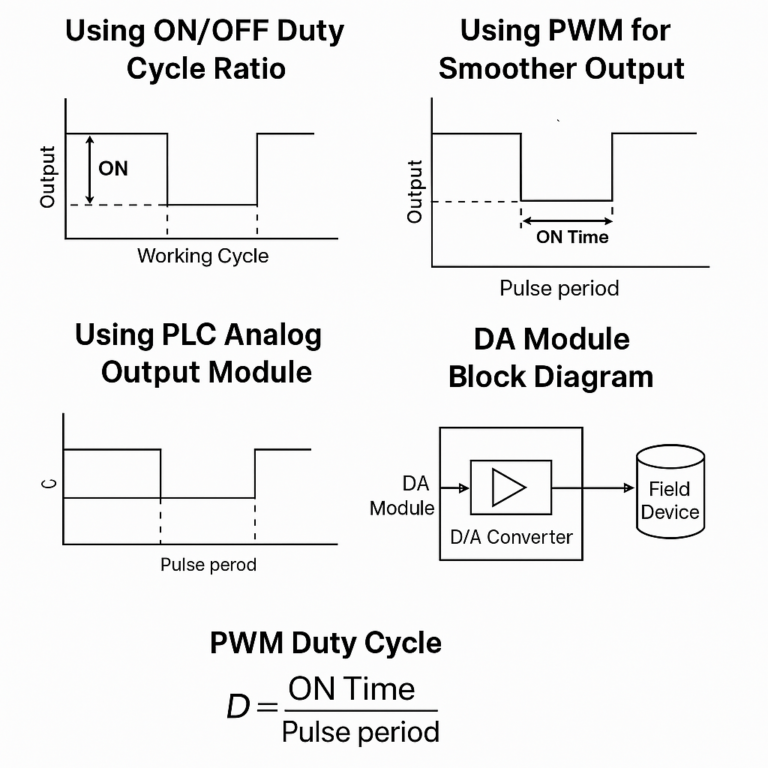
1. Using ON/OFF Duty Cycle Ratio to Simulate Analog Output
This is the most basic way to achieve analog-like behavior without an analog output module. The principle is to use a digital output to toggle ON and OFF in a fixed cycle, with the ON/OFF time ratio (duty cycle) representing the analog value.
Working Principle
The controlled device receives a pulsed signal.
The power delivered over time depends on the ratio of ON time to total cycle time.
Shorter cycles lead to smoother output and less fluctuation.
PLC Implementation
Typically, this method uses two timers:
Timer 1: Defines the total working cycle.
Timer 2: Defines the ON period within that cycle.
When ON time < working cycle → Partial output When ON time ≥ working cycle → Continuous output
Advantages
Cost-effective; no analog output module required.
Simple to implement with standard PLC digital outputs.
Limitations
The output is discontinuous, leading to fluctuations.
Not suitable for precision control.
If relay outputs are used, frequent switching shortens lifespan.
2. Using PWM (Pulse Width Modulation) for Smoother Output
For PLCs with transistor outputs, PWM provides a more stable and reliable way to simulate analog output.
Working Principle
Output a high-frequency pulse train.
Adjust the duty cycle (D):
Features
More continuous power delivery compared to basic ON/OFF method.
Suitable for applications with heating elements, motors, or lighting where precise power control is needed.
Benefits
No need for a DA (Digital-to-Analog) module.
High output stability if pulse frequency is high enough.
3. Using PLC Analog Output Modules (DA Units)
For precise and continuous analog control, the best option is a dedicated analog output module (also known as DA or DAC module).
Function
Converts internal digital values into real-world analog signals like:
Voltage: 0–10V, ±10V, 1–5V
Current: 4–20mA
Output can be connected directly to actuators, indicators, or control loops.
Resolution and Precision
Common resolutions: 8-bit, 12-bit, 16-bit
8-bit → 1/255 of range
12-bit → 1/4095
16-bit → 1/65535
Higher resolution = better precision
Internal Workflow
The PLC CPU sends digital values via the backplane bus.
The DA module stores the value in its internal memory.
The value is converted via D/A conversion circuits.
The analog signal is output to the field device.
Opto-isolated outputs enhance noise immunity and stability.
Common Channel Configurations
1, 2, 4, or 8 channels per module.
Advanced Functions
Output Limiting: Sets upper/lower output bounds.
Limit Alarms: Triggers if output exceeds defined thresholds.
Pulse Output Mode: Converts analog output into a pulse signal with proportional duty cycle.
Using an Analog Output Module: Three Key Steps
1. Selection
Match module to PLC series and required signal type (voltage or current).
Choose proper resolution and channel count.
2. Wiring
Follow terminal markings (voltage and current terminals are often separate).
Use shielded cables and proper grounding to reduce interference.
3. Configuration
Some modules use DIP switches (hardware setup).
Others use software settings in the PLC program to define:
Signal range
Channel assignments
Alarm thresholds
Improper configuration is like leaving the device unconnected—functions won’t work correctly without it.
Conclusion
Whether you’re working with a basic control system or a complex automation setup, PLC analog output can be realized through multiple methods depending on precision needs and hardware availability:
Method
Hardware Needed
Precision
Application
ON/OFF Duty Cycle
Digital Output
Low
Basic heating, lighting
PWM Output
Transistor Output
Medium
Small motors, resistive loads
Analog Output Module (DA)
DA Module
High
Actuators, VFDs, proportional valves
Choosing the right method ensures both performance and cost-efficiency in your automation projects.