Thermocouples are widely used in industrial environments as reliable temperature sensors. However, due to harsh working conditions and system complexities, they can occasionally encounter faults that affect measurement accuracy. This guide outlines common symptoms of thermocouple failures—abnormally low or high temperature readings—and provides step-by-step troubleshooting methods.
🔧 Problem 1: Displaying Minimum Temperature
When the temperature display shows a very low or even negative value, it could be due to reversed polarity or input signal issues. In instruments like the AI series digital display meter, this is often indicated as:
Upper PV window: Displays a negative temperature.
Lower SV window: Flashes and alternately shows “orAL” and the setpoint value.
✅ Troubleshooting Steps:
Polarity Check:
Reverse the thermocouple signal wiring and observe the display.
If the issue resolves, polarity was incorrect.
Input Terminal Short Test:
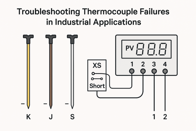
Short-circuit terminals 2 and 3 on the display meter.
If the display returns to ambient temperature and the SV window stops flashing, the meter is functioning properly.
Thermocouple Type Identification:
When polarity markings are not visible:
S-type or R-type: Gently bend the electrodes — the softer one is negative.
K-type or N-type: Use a magnet — the magnetic one is negative.
J-type: The magnetic one is positive.
🚨 Problem 2: Displaying Maximum Temperature
If the display exceeds the instrument’s upper limit, with the PV window showing a high value and the SV window flashing “orAL”, this typically indicates an open circuit or configuration error.
✅ Possible Causes and Remedies:
Open Circuit Detection:
Many instruments have built-in sensor break detection. If the thermocouple or wiring is disconnected, the display will show maximum temperature.
Testing Method:
Short terminals XS1 and XS2; if ambient temperature is displayed, the input side is intact.
Disconnect the thermocouple from terminal 1 and use a multimeter to check resistance between the thermocouple and terminal 2.
Infinite or very high resistance indicates open circuit or poor contact.
Wiring Issues:
Check all screw terminals, especially inside the thermocouple junction box.
Oxidation, corrosion, or loose screws due to high-temperature or humid environments may lead to poor conductivity.
Mismatched Thermocouple Type:
Ensure the thermocouple and the digital meter are configured with the same thermocouple type (e.g., K, J, S, etc.).
Check all related settings: sensor type, input range, and calibration parameters.
🧠 Pro Tips for Technicians
Always verify sensor type settings after installing or replacing a thermocouple or display unit.
Use shielded compensating cables with proper grounding to prevent interference.
Inspect hidden junction screws inside terminal blocks — they are a common point of failure often overlooked.
✅ Conclusion
When facing abnormal thermocouple readings, adopt a structured troubleshooting approach:
Check polarity
Test for open circuits
Inspect connection quality
Verify configuration parameters
Systematic diagnosis ensures accurate fault location, faster repairs, and reduced downtime in your industrial operations.