RTD (Resistance Temperature Detector) temperature transmitters are widely used in industrial automation for precise temperature measurement. Proper wiring is essential to ensure measurement accuracy and system stability. This guide explains wiring principles and methods for different RTD and transmitter configurations, including practical tips and troubleshooting advice.
1. 🔧 Basic Wiring Principles
1.1 Common RTD Types
Pt100 (Platinum 100Ω) is the most commonly used RTD sensor.
Accuracy classes:
Class A: ±0.15°C at 0°C
Class B: ±0.3°C at 0°C
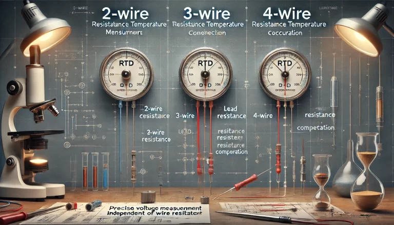
RTDs may have 2, 3, or 4 wires, depending on the application and required precision.
1.2 Transmitter Power Supply
Most transmitters use 24V DC.
2-wire transmitters: Power and signal share the same two wires.
4-wire transmitters: Power and signal are independent.
1.3 Output Signal Types
4–20 mA (most common, especially with 2-wire transmitters)
0–5 V or 0–10 V (often in 4-wire transmitters)
Ensure compatibility with input terminals of control systems (PLC, DCS, etc.).
2. 🔌 Wiring Methods by Configuration
2.1 Three-Wire RTD + Two-Wire Transmitter (Most Common Setup)
RTD Terminals: 3 wires (commonly Red, Red, Black or labeled A, B, C)
Transmitter Terminals:
| Terminal | Function |
|---|---|
| +24V | Power supply positive |
| OUT+ | Signal output (same as +24V) |
| OUT- | Common ground |
| R1, R2, R3 | RTD wiring terminals |
Wiring Steps:
Connect the two same-color wires (e.g., Red, Red) to R1 and R3.
Connect the third wire (e.g., Black) to R2.
Connect +24V and OUT- to the power supply.
OUT+ goes to the signal input of the receiving device (e.g., PLC).
✅ This setup helps eliminate lead wire resistance error through compensation.
2.2 Two-Wire RTD + Four-Wire Transmitter
RTD Terminals: 2 wires only
Transmitter Terminals:
| Terminal | Function |
|---|---|
| 24V+, 24V- | Power input |
| OUT+, OUT- | Signal output |
| EXC+, EXC- | Excitation (current source) |
Wiring Steps:
Connect the two RTD wires to EXC+ and EXC-.
Power and signal wiring are completely independent.
⚠️ Note: Measurement accuracy is lower due to uncompensated lead resistance. Avoid in precision applications.
2.3 Four-Wire RTD + Four-Wire Transmitter (For High-Precision Use)
RTD Terminals: 4 wires
Two for excitation (current)
Two for sensing (voltage drop)
Transmitter Terminals:
| Terminal | Function |
|---|---|
| EXC+, EXC- | Excitation current supply |
| V+, V- | Voltage measurement inputs |
Wiring Steps:
Connect two excitation wires to EXC+ and EXC-.
Connect two sensing wires to V+ and V-.
✅ Ideal for long-distance or high-accuracy measurements, as voltage drop is measured directly, unaffected by wire resistance.
3. ⚠ General Wiring Tips
Cable Type: Use shielded twisted pair cables. Ground the shield at one end to reduce electromagnetic interference (EMI).
Wire Consistency: For 3-wire or 4-wire RTDs, make sure the same-color wires have equal resistance (usually factory-matched).
Polarity Check: Verify correct polarity before powering up. Incorrect wiring may damage the transmitter.
Short Circuit Test: Inspect for short circuits, especially under humid or dusty conditions.
Configuration: Some transmitters require manual or software configuration for:
RTD type (e.g., Pt100 or NTC)
Measuring range (e.g., -50°C to 150°C)
4. 🔄 Sample Wiring Diagram: 3-Wire RTD + 2-Wire Transmitter
| Transmitter Terminal | Connected To | Description |
|---|---|---|
| +24V | Power Supply + | Supplies DC power |
| OUT+ | Signal Output to PLC/DCS | Transmits 4–20 mA signal |
| OUT- | Power Supply – | Ground/common |
| R1 | RTD wire 1 (Red) | First excitation line |
| R2 | RTD wire 2 (Black) | Sensing line |
| R3 | RTD wire 3 (Red) | Second excitation line |
5. 🛠 Troubleshooting Guide
| Symptom | Possible Cause | Suggested Action |
|---|---|---|
| No Output | Power disconnected or loose wiring | Check power supply and terminal contacts |
| Abnormal Output | Wire short circuit, incorrect settings or grounding | Verify wiring, shield ground, recheck config |
| No RTD Response | Sensor open circuit or damaged | Use multimeter to check resistance (~100Ω for Pt100 at 0°C) |
6. 📚 Final Notes
Always refer to the manufacturer’s manual for terminal labeling and pin definitions, as they may vary between brands.
Ensure proper grounding of the transmitter housing to reduce common-mode noise in industrial environments.