To effectively monitor and control an industrial process, it is essential to measure parameters such as temperature, pressure, flow, and liquid level in real time. The instruments used to perform these measurements are referred to as measurement instruments or sensing devices, and they include:
Indicating Instruments: Provide real-time readings.
Transmitters: Convert physical parameters into standardized electrical signals (e.g., 4–20mA, 0–10V) for further processing.
For different measured parameters, the types of instruments vary. Even for the same parameter, multiple measurement principles and corresponding instruments may exist. Despite the wide variety of instruments, their performance is typically evaluated using several common technical specifications. Below are six of the most important ones:
1. Absolute Error
Definition: The absolute error (Δ) is the difference between the instrument’s displayed value (X) and the true value of the measured quantity (Xt):
Δ=X−Xt
Note: In practice, the true value XtX_tXt is often unknown or unattainable. Therefore, a highly accurate reference instrument (standard meter) is used to obtain a reference value X0X_0X0, replacing XtX_tXt:
Δ=X−X0
The maximum absolute error (Δmax) is the largest absolute error observed across the entire measurement range of the instrument.
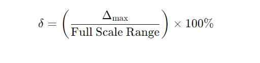
2. Basic Error (Relative Error Based on Full Scale)
Also known as reference error or percentage of full-scale error, this is a normalized form of absolute error, defined as:
Where:
Full Scale Range = Upper Limit – Lower Limit of the instrument’s measuring span
This specification is commonly expressed as ±%FS (Full Scale).
3. Accuracy Class
Accuracy is a key indicator of instrument quality and defines how closely the measured value matches the true value. National and international standards often define accuracy in terms of accuracy classes, such as:
0.05, 0.1, 0.2, 0.5, 1.0, 1.5, 2.5, etc.
The smaller the number, the higher the accuracy.
Accuracy Class Determination:
To determine the accuracy class, remove the ± and % signs from the basic error. For example:
An instrument with a basic error of ±1.0% has an accuracy class of 1.0
If the basic error is ±1.3%, the accuracy class is rounded up to 1.5
Typical usage:
High-precision instruments (e.g., 0.005 class) are used as reference standards
Field instruments commonly range between 0.5 to 2.5 in accuracy class
Accuracy class is usually marked on the instrument’s front panel using symbols or digits.
4. Sensitivity and Resolution
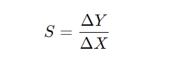
Sensitivity (S)
For analog (pointer-type) instruments, sensitivity refers to how responsive the instrument is to changes in the measured parameter:
Where:
ΔY: Displacement of the pointer (linear or angular)
ΔX: Corresponding change in the measured quantity
A higher sensitivity means the pointer moves more for small changes in input.
Sensitivity Threshold (Dead Zone):
The smallest change in the measured variable that can produce a visible movement of the pointer. If the change is below this value, the pointer will not respond — this is called the dead zone.
Resolution (for Digital Instruments)
Resolution describes the smallest distinguishable increment on a digital display.
For a 4-digit digital instrument, resolution is 1/10,000 of the full range.
The higher the number of display digits, the higher the resolution.
Displayable Limit (Discrimination Threshold)
Also called discrimination or minimum displayable unit, this refers to the smallest measurable value that the instrument can display. For example, if the last digit on a digital temperature meter represents 0.1°C, the discrimination threshold is 0.1°C.
5. Hysteresis (Backlash or Reversal Difference)
Hysteresis refers to the maximum difference between readings during a rising and falling measurement cycle, under identical conditions. It reflects the instrument’s ability to return the same output for the same input, regardless of direction.
Causes of Hysteresis:
Mechanical play or friction in moving parts
Elastic hysteresis of components (e.g., Bourdon tubes or springs)
Hysteresis is an important factor affecting repeatability and reliability.
6. Response Time
Response time is the time it takes for an instrument to respond to a sudden change in the input signal and stabilize at a new reading.
Usually defined as the time required for the instrument to reach 95% of its final value after a step input is applied.
A shorter response time means faster dynamic behavior and better suitability for real-time monitoring and control.
✅ Summary
Understanding these six key technical specifications — absolute error, basic error, accuracy, sensitivity & resolution, hysteresis, and response time — is essential when selecting, comparing, or calibrating industrial measurement instruments. These parameters determine the reliability, consistency, and suitability of an instrument for specific process control tasks.
If you’re choosing instruments for a critical application, always ensure their technical specifications match your process requirements and standards.