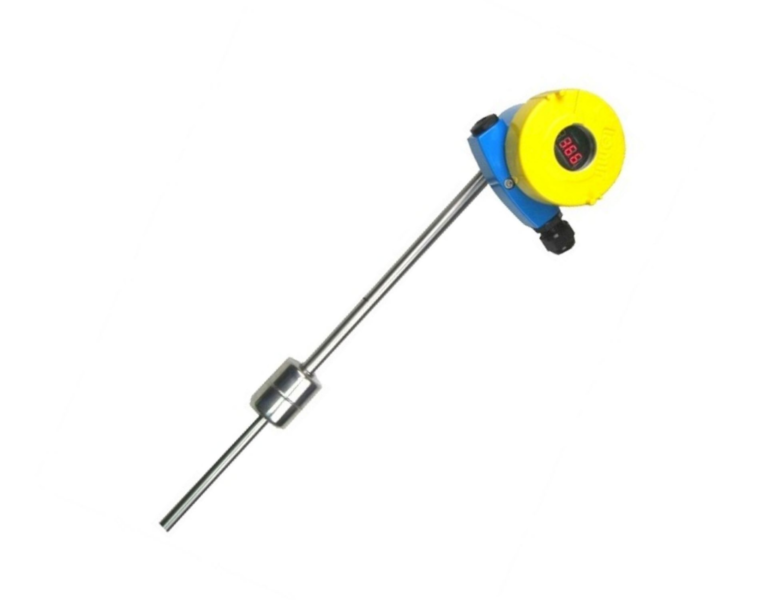
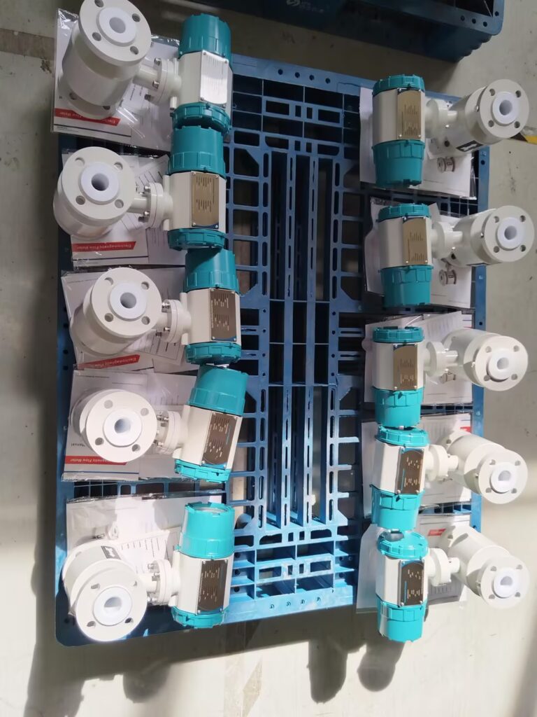
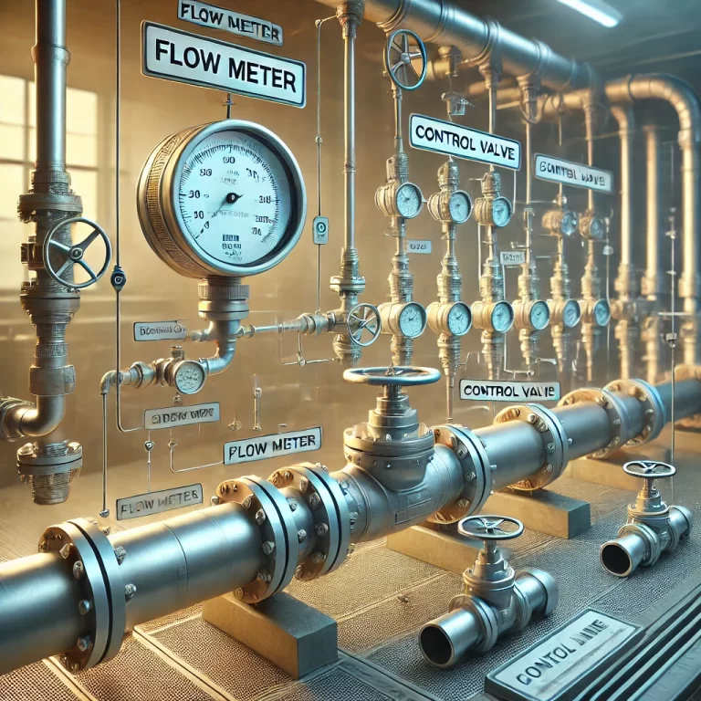
Instrument Maintenance and Inspection Procedures / Instrumentation General GuidelinesAll inspections and maintenance tasks must be conducted by qualified personnel only.Maintenance work shall be carried out only after obtaining clearance from operations personnel.All observations and corrective actions must be recorded in the maintenance logbook.Use appropriate PPE and follow safety protocols at all times. 1. Safety Barrier Maintenance1.1 Visual InspectionEnsure the safety barrier casing is clean, free of dust or contaminants.All components must be intact with no signs of physical damage.Nameplate and labels must be legible and complete.No signs of overheating, abnormal smell, or discoloration.Terminal connections must be tight with no loose wiring.Wiring must be neat and correctly labeled.1.2 Routine & Periodic MaintenanceMonthly: Perform surface cleaning and check for proper wiring integrity.Monthly: Verify instrument power supply is stable and within rated voltage.Annually: Check basic operational accuracy and barrier calibration (if applicable).Monthly: Inspect signal input/output wiring for continuity, short circuits, and insulation condition. 2. Float Type Level Gauge2.1 Visual InspectionInspect external housing, labels, and nameplate—must be clean, legible, and intact.Ensure dial and pointer are readable and not deformed.Internally, the PCB and terminal screws must be tight and wiring correct.Check for signs of corrosion, moisture ingress, or broken insulation on wiring.Inspect thread integrity at electrical interfaces and ensure sealing is proper.Verify flange connections are tight with no leaks.Confirm drain valve is functional and not clogged.2.2 Routine & Periodic MaintenanceWeekly: Clean the instrument and surrounding area.Weekly: Inspect upper and lower flange joints for any leakage.Monthly: Inspect transmitter components for damage or rust; verify all labels.Monthly: Inspect the signal loop for open/short circuits and insulation integrity.Monthly: Verify display and zero point accuracy.As Scheduled: Calibrate according to the gauge calibration cycle.Winter Season: Check heat tracing and insulation systems to prevent freezing or blockage. 3. Electromagnetic Flow Meter3.1 Visual InspectionConfirm all identification marks are clear; inspect body, nameplate, and casing.Internally check circuit boards, terminals, cable entry—must be clean and secure.Check electrical thread connections for damage or loose fitting.Ensure flange seals are leak-free.3.2 Routine & Periodic MaintenanceWeekly: Clean the flow meter housing and surrounding area.Weekly: Inspect flange joints for leaks or gasket damage.Monthly: Check for mechanical integrity and corrosion on body and fasteners.Monthly: Verify electrical loop and signal circuit reliability.Monthly: Confirm zero drift and display values match actual flow.Scheduled: Calibrate according to manufacturer’s recommended interval.Winter Season: Ensure heat tracing is functioning to prevent blockage or freezing. 4. Control Room Cabinet Fan4.1 Visual InspectionClean exterior; ensure protective grill is secure.Filter should be clean, undamaged, and unobstructed.Labels and nameplates must be legible.4.2 MaintenanceMonthly: Clean the air filters.Weekly: Check for abnormal fan noise or vibration. Add lubrication or repair if needed. 5. Field Temperature Gauge5.1 Visual InspectionCheck for clean and rust-free casing; pointer and scale should be readable.Confirm no leakage at probe connection; inspect thread integrity.5.2 Routine MaintenanceWeekly: Clean the instrument and check for leakage at joints.Monthly: Inspect components for corrosion or damage.Monthly: Verify pointer accuracy.Scheduled: Perform calibration as per the specified cycle. 6. Control Valve6.1 Visual InspectionCheck casing, nameplate, and gland area for leaks or damage.Valve positioner should be clean with secure cable entry.Confirm air supply is stable and all fittings are leak-free.6.2 Routine MaintenanceWeekly: Clean valve and actuator body.Weekly: Check flange and gland packing for leaks.Monthly: Verify component integrity, labeling, and air fittings.Monthly: Check stroke accuracy and feedback signal consistency.Scheduled: Calibrate valve as per defined interval.Seasonal: Inspect heat tracing and insulation for freeze protection. 7. Pressure Gauge7.1 Visual InspectionCheck nameplate, lens clarity, and cleanliness.No cracks, moisture, or foreign material inside gauge.Confirm pressure tap and fitting are leak-free.7.2 MaintenanceWeekly: Clean instrument and check for leaks in tap line.Monthly: Inspect parts for corrosion, label accuracy, and fastener tightness.Monthly: For oil-filled gauges, inspect for leaks or oil level changes.Scheduled: Send for recalibration as per interval.If Not in Use: Remove gauge, seal with plug, and close root valve. 8. Pressure Transmitter8.1 Visual InspectionInspect casing, label, and enclosure sealing.Internal wiring and PCB must be clean and correctly connected.Check for thread wear or loose connectors.8.2 Routine MaintenanceWeekly: Clean transmitter and ensure probe/tap line is leak-free.Monthly: Check terminal tightness, label visibility, and signal continuity.Monthly: Verify measurement accuracy and zero stability.Scheduled: Calibrate according to calibration plan.Periodically:Drain condensate and purge impulse lines.Refill seal fluid for isolation systems if applicable.Blowdown impulse lines for clogging media.When Idle: Shut root valve and protect instrument from ingress.Winter: Ensure impulse line heating/insulation is intact to avoid freezing damage. 9. Combustible Gas Detector9.1 Visual InspectionConfirm sensor and housing are intact; labels should be legible.Inspect internal wiring, terminals, and connectors for cleanliness and tightness.9.2 MaintenanceWeekly: Clean the detector housing and sensor head.Weekly: Verify zero reading is within ±3% LEL.Monthly: Inspect components for corrosion or damage.Monthly: Check I/O signal integrity and insulation resistance.Scheduled: Calibrate gas sensors as per gas type and manufacturer recommendation. Share This Story, Choose Your Platform! Contact Us Please prove you are human by selecting the cup. Request a Quote