Introduction
Data types play a critical role in both computer science and industrial automation. They define how data is stored, transmitted, and interpreted. Common data types include:
Integer Types:
Signed Integer: Represents both positive and negative numbers (e.g.,
int16,int32).Unsigned Integer: Represents only positive numbers (e.g.,
uint16,uint32).
Floating-Point Types:
Single Precision (Float): Typically 32-bit, used for fractional values.
Double Precision (Double): Typically 64-bit, offering higher accuracy.
Boolean Type:
Represents binary states:
True(1) orFalse(0), usually stored as a single bit.
Character Type:
Represents a single character, typically stored in 8 bits.
String Type:
A sequence of characters, variable in length.
Array Type:
A collection of elements of the same data type.
Structure Type:
A group of different data types combined into a single entity.
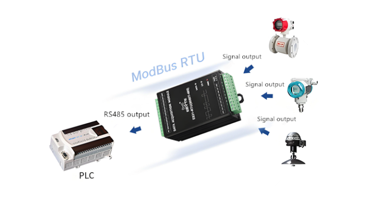
In industrial automation, data communication protocols like Modbus are used to transmit various data types between devices. Understanding the supported Modbus data types is crucial for effective implementation.

Common Data Types in Modbus
The Modbus protocol, widely used in industrial automation, supports several key data types. These data types are mapped to specific Modbus function codes, which define how data is read and written.
| Data Type | Format | Function Codes | Description |
|---|---|---|---|
| Coil Status | Boolean | 01 (Read), 05 (Write Single), 15 (Write Multiple) | Represents discrete outputs such as relays, switches, or actuators. |
| Discrete Input | Boolean | 02 (Read) | Represents discrete inputs such as push buttons, sensors, or status signals. |
| Holding Register | uint16, int16, float32 | 03 (Read), 06 (Write Single), 16 (Write Multiple) | Stores configuration parameters, measured values, and control setpoints. |
| Input Register | uint16, int16, float32 | 04 (Read) | Stores read-only sensor data, device states, and measurement values. |

Detailed Explanation of Modbus Data Types
1. Coil Status (Boolean)
Value Range:
0(Off) or1(On)Application: Used for controlling and monitoring discrete outputs, such as turning motors, lights, or solenoids on/off.
Storage: Typically occupies 1 bit in the Modbus memory map.
2. Discrete Input (Boolean)
Value Range:
0(False) or1(True)Application: Represents binary input signals from devices such as sensors, emergency stops, or push buttons.
Storage: Uses a single bit per input.
3. Holding Registers (16-bit Integer and 32-bit Float)
Common Data Formats:
Unsigned 16-bit Integer (
uint16): Range0to65535, used for status codes, counters, or simple settings.Signed 16-bit Integer (
int16): Range-32768to32767, used for signed values like temperature and pressure.32-bit Floating Point (
float32): IEEE 754 standard, often stored using two consecutive 16-bit registers.
Application: Stores control parameters, calibration settings, and measured values.
Storage: Each register is 16 bits, but 32-bit values require two registers.
4. Input Registers (16-bit Integer and 32-bit Float)
Common Data Formats: Same as Holding Registers.
Application: Used for sensor readings and read-only device states.
Storage: Each input register is 16 bits.

Data Storage and Endianness in Modbus
One important aspect to consider when working with Modbus data is the byte order (Endianness). Modbus traditionally follows a Big-Endian format (higher byte stored first), but some implementations may use Little-Endian.
For example, a 32-bit floating-point number stored in two consecutive 16-bit registers might have different representations:
Big-Endian (Modbus standard):
Register 1 = High Word,Register 2 = Low WordLittle-Endian:
Register 1 = Low Word,Register 2 = High Word
Understanding the byte order of a device is critical when interpreting floating-point values.
Reading and Writing Modbus Data
1. Read Operations
Function Codes:
01,02,03,04Example: Reading a temperature value stored in a Holding Register (
int16):Request: Read register
40001Response:
0x07D0(decimal2000, representing20.00°Cif a scale factor of0.01is applied)
2. Write Operations
Function Codes:
05,06,15,16Example: Writing a setpoint value (
uint16) to a Holding Register:Request: Write
5000to register40002Response: Acknowledgement confirming the write operation
Practical Considerations for Modbus Data Handling
Ensure correct function codes: Different devices may only support specific function codes.
Verify data scaling: Some values require scaling factors (e.g., temperature in
°Cstored asx100).Handle word order in 32-bit values: When dealing with floats or long integers, confirm register order.
Check device documentation: Modbus implementation varies by manufacturer, so always reference device-specific manuals.

Conclusion
The Modbus protocol supports multiple data types, including Boolean, integer, and floating-point values. Understanding these data types is essential for designing efficient and accurate Modbus communication systems in industrial automation. By knowing how data is stored, transmitted, and interpreted, engineers can ensure seamless integration between Modbus devices and control systems.