Introduction
The HART (Highway Addressable Remote Transducer) protocol is a widely used communication standard in industrial process control systems. It enables digital communication between field instruments, such as transmitters and controllers, over traditional 4-20mA analog signal loops. When performing offline debugging or configuration using a HART communicator, a 250Ω resistor must be inserted in series with the power supply. This article explains the necessity of this resistor and its role in ensuring successful communication.
Understanding the HART Communication Protocol
The HART protocol utilizes frequency shift keying (FSK) modulation to superimpose digital signals onto a standard 4-20mA analog signal. The digital signals are transmitted using two distinct frequencies:
1200 Hz represents a binary ‘1’
2200 Hz represents a binary ‘0’
Since these signals are superimposed on the 4-20mA current loop, they require a certain impedance in the circuit to avoid being attenuated or short-circuited.
The Role of the 250Ω Resistor
When using a HART communicator for offline debugging, a 250Ω resistor must be connected in series with the power supply and the field instrument. The reasons for this requirement include:
1. Providing the Necessary Impedance for FSK Signal Transmission
The HART protocol specifies that the minimum required impedance in the loop must be at least 230Ω to properly transmit the FSK signal. If the impedance is too low (close to 0Ω), the FSK signal will be absorbed by the low resistance, preventing the HART communicator from successfully detecting and decoding the data. The 250Ω resistor ensures that the circuit meets the impedance requirement.
2. Ensuring Signal Integrity and Avoiding Attenuation
Without a proper resistance in the loop, the HART digital signal may become severely attenuated, making it difficult for the HART communicator to interpret the transmitted data. The resistor acts as a load, stabilizing the communication by preventing excessive signal loss.
3. Preventing Power Supply from Acting as a Short Circuit
Most standard DC power supplies have very low internal impedance, typically in the range of a few ohms or less. If a HART communicator is connected to a circuit without sufficient impedance, the power supply effectively shorts out the communication signals, making data exchange impossible.
How to Properly Connect the 250Ω Resistor
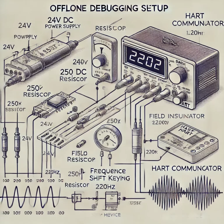
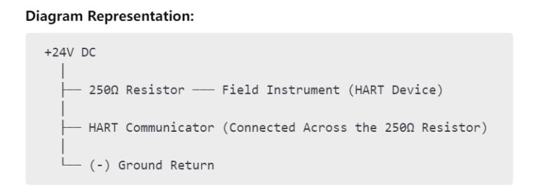
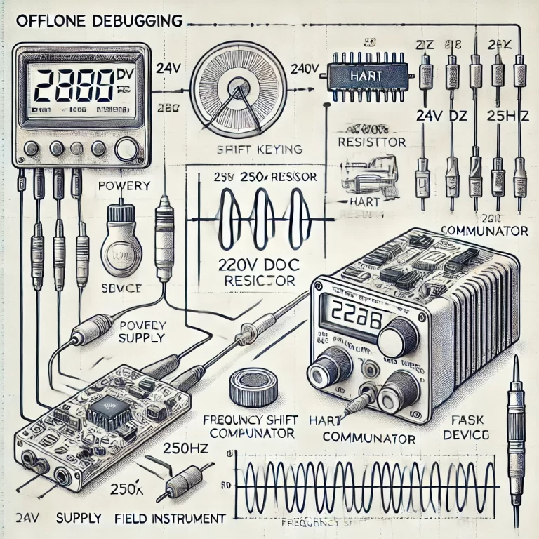
For offline debugging, the setup should be wired as follows:
Power Supply (24V DC) → 250Ω Resistor → Field Instrument (HART Device) → Power Return (-)
The HART communicator should be connected in parallel with the 250Ω resistor to detect the modulated signals.
Special Cases and Considerations
Using a DCS or PLC System:
Many modern Distributed Control Systems (DCS) or Programmable Logic Controllers (PLC) already incorporate an internal resistance in their analog input modules. In such cases, an additional external 250Ω resistor may not be necessary.
Using a Smart Power Supply:
Some dedicated HART-compatible power supplies are designed with the required impedance built-in. If using such a power supply, an external resistor may not be needed.
Resistance Value Variation:
The 250Ω value is a standardized recommendation, but values between 230Ω and 600Ω can still allow HART communication in some setups. However, deviating too far from 250Ω may reduce reliability.
Conclusion
The inclusion of a 250Ω resistor in a HART communication loop is critical for ensuring successful signal transmission. It prevents attenuation, avoids power supply short-circuiting, and provides the necessary impedance for FSK signals. Understanding this requirement helps engineers and technicians effectively set up and troubleshoot HART-compatible devices in industrial automation and process control systems.