1. Introduction
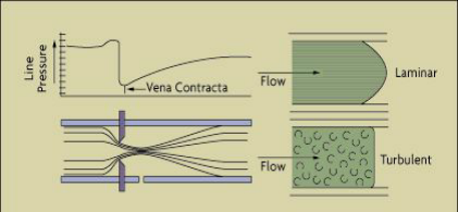
Orifice flow meters are widely used in industrial flow measurement due to their simplicity, reliability, and cost-effectiveness. They function based on the principle of differential pressure, where the fluid flow rate is determined by measuring the pressure drop across an orifice plate. Proper installation is crucial to ensure accurate readings and long-term performance. This document outlines the key installation guidelines, common errors, and best practices.
2. Selection of Installation Location
2.1 Straight Pipe Requirements
To ensure stable flow conditions and minimize disturbances, the orifice flow meter should be installed in a straight pipe section with sufficient upstream and downstream lengths:
The upstream straight pipe length should be at least 10 times the pipe diameter (D).
The downstream straight pipe length should be at least 5 times the pipe diameter (D).
If there are flow-disturbing elements (e.g., elbows, valves, reducers) upstream, the straight pipe length should be increased accordingly to reduce turbulence.
2.2 Avoidance of Unfavorable Locations
Avoid installing the meter at the highest or lowest points in the pipeline to prevent gas or liquid accumulation, which can impact accuracy.
For gas flow measurement, the pressure taps should be located on the upper part of the pipe.
For liquid flow measurement, the pressure taps should be placed on the lower part of the pipe.
For steam flow measurement, the pressure taps should be positioned on the side of the pipe to prevent condensate from affecting the readings.
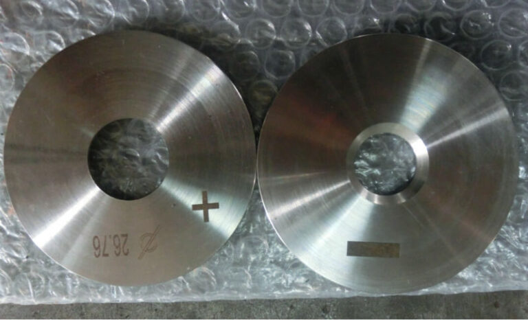
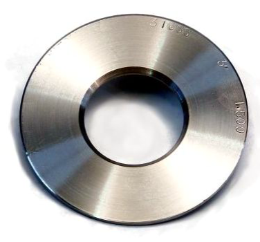
3. Orifice Plate Installation
3.1 Alignment and Positioning
The orifice plate’s centerline must align precisely with the pipeline’s centerline.
The upstream face of the orifice plate should be perpendicular to the pipe axis, with a deviation not exceeding 1°.
3.2 Orientation of the Orifice Plate
The sharp edge (upstream side) of the orifice plate must face the incoming flow.
A common mistake is reversing the orientation, which leads to inaccurate measurements and increased pressure losses.
3.3 Sealing Considerations
Use appropriate gaskets to ensure a proper seal and prevent leaks.
The gasket must not protrude into the pipe, as it can alter the flow pattern and introduce measurement errors.
4. Pressure Tapping and Impulse Piping Installation
4.1 Selection of Pressure Tapping Method
The common pressure tapping methods include:
Corner taps (suitable for smaller pipes)
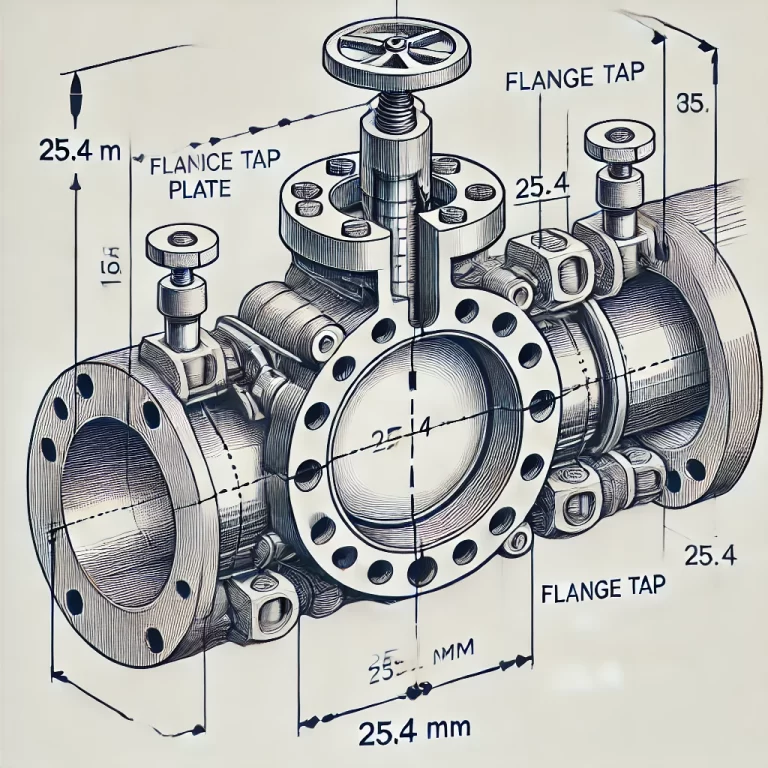
Flange taps (commonly used in industrial applications)
D-D/2 taps (used for large pipeline systems)
The selection depends on the system design and accuracy requirements.
4.2 Impulse Piping Installation Guidelines
Use short and straight impulse lines to reduce response time and minimize pressure drop.
The inner diameter of impulse pipes should be at least 6 mm.
For horizontal piping, maintain a slight slope (not less than 1:10) to facilitate drainage and prevent blockages.
For gas flow measurement, impulse lines should be routed upward from the pressure taps to prevent liquid accumulation.
For liquid flow measurement, impulse lines should be routed downward to avoid gas pockets.
Apply insulation and heating to impulse lines if necessary to prevent condensation, freezing, or vaporization.
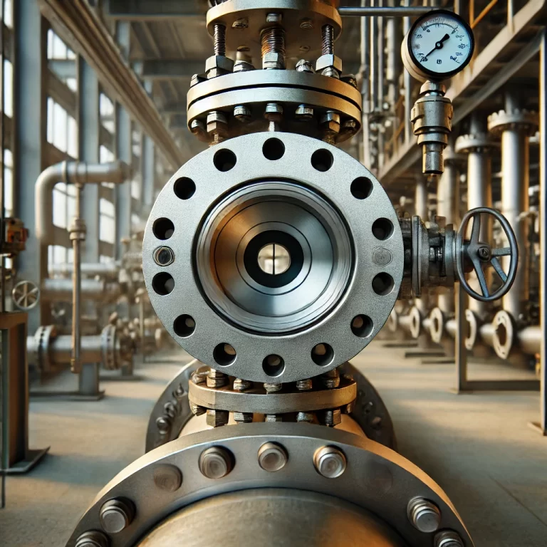
5. Differential Pressure Transmitter Installation
The transmitter should be installed as close to the orifice plate as possible to minimize pressure signal loss.
Maintain the same elevation as the pressure taps to avoid errors caused by height differences. If unavoidable, apply correction factors in the measurement system.
Ensure easy access to the transmitter for maintenance and calibration.
6. Common Installation Errors and How to Avoid Them
| Common Mistake | Impact | Prevention |
|---|---|---|
| Incorrect orifice plate orientation | Inaccurate readings due to improper flow characteristics | Ensure sharp edge faces incoming flow |
| Insufficient straight pipe length | Turbulence causes unstable measurements | Follow recommended upstream/downstream pipe lengths |
| Pressure taps installed at incorrect positions | Air or liquid pockets distort readings | Follow guidelines for correct pressure tap placement |
| Impulse lines too long or improperly sloped | Signal delay, blockages, or measurement errors | Keep impulse lines short, straight, and properly sloped |
| No insulation for impulse lines in steam systems | Condensation leads to fluctuating readings | Use proper insulation and heat tracing where needed |
7. Conclusion
Proper installation of an orifice flow meter is crucial for accurate measurement and long-term reliability. By following the recommended guidelines for pipe straight lengths, plate alignment, impulse line routing, and transmitter installation, measurement errors can be minimized. Regular inspection and maintenance further ensure optimal performance.
For complex installations, always refer to manufacturer recommendations and industry standards (such as ISO 5167) to achieve the best results.