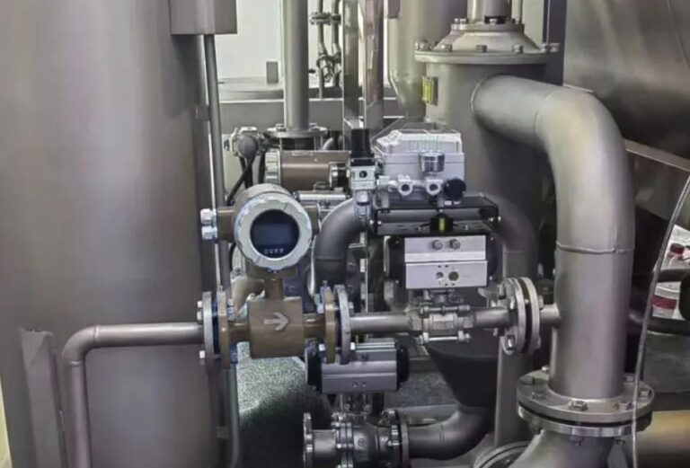
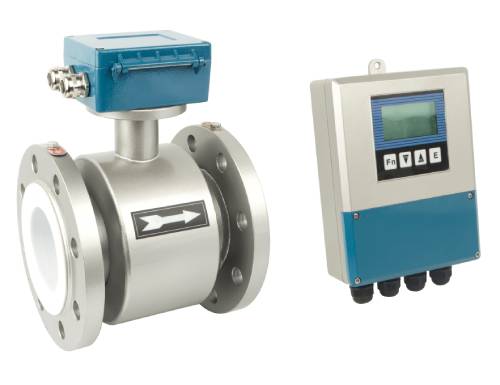
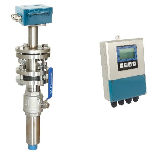
Electromagnetic flow meters are widely used in industries where precise measurement of liquid or gas flow is essential. The coil resistance of these devices plays a crucial role in ensuring their accurate operation. The resistance values of the coils can vary depending on the model, manufacturer, and specifications, usually ranging from tens of ohms to hundreds of ohms. Here’s a detailed guide on how to evaluate the coil resistance of an electromagnetic flow meter.

1. Typical Coil Resistance Range
The coil resistance of electromagnetic flow meters typically falls within the range of 50Ω to 200Ω, though it may vary based on the type and specifications of the flow meter. To determine the correct resistance range, you need to consult the product’s manual or the technical specifications provided by the manufacturer. The resistance can be influenced by factors such as the material used for the coil, the dimensions of the coil, and the operating environment.
Specific Values
- Standard electromagnetic flow meters usually have resistance values ranging from 50Ω to 200Ω.
- Specialized models might have values outside this typical range, depending on their intended application and the specifications of the device.

2. How to Measure Coil Resistance
a. Ensure Power is Off
Before proceeding with any measurements, ensure the flow meter is powered off to prevent electrical hazards and to ensure accuracy during measurement. Measuring the coil resistance while the device is powered on could lead to incorrect readings or potential damage to the meter.
b. Using a Multimeter
A digital multimeter is the most common tool used to measure coil resistance. Follow these steps:
- Set the multimeter to measure resistance (ohms).
- Place the multimeter probes at the two terminals of the coil.
- Read the resistance value displayed on the multimeter.
c. Checking the Resistance at Both Coil Ends
In cases where the coil has two separate sections, make sure to measure the resistance at both ends of the coil. This ensures that the coil is intact and that no short circuits or breaks are present.
3. Factors Affecting Coil Resistance Measurements
Several factors can influence the accuracy and reliability of your resistance measurements. It is important to be aware of these to avoid erroneous readings.
a. Temperature Impact
The resistance of the coil can fluctuate depending on the temperature. As temperature rises, the resistance usually increases. This change needs to be considered during measurement, particularly if the flow meter is used in environments with varying temperatures.
- Recommendation: If possible, perform the resistance measurement in a controlled environment or account for ambient temperature changes during measurement.
b. Comparison with Manufacturer’s Standard
Once you have measured the resistance, compare the result with the standard values provided by the manufacturer. This helps to determine whether the coil resistance falls within the acceptable range for the specific model of the flow meter.
- If the resistance is outside the specified range, further investigation may be necessary to check for possible faults in the coil.

4. Diagnosing Coil Faults
If the resistance values significantly deviate from the standard range, it could indicate that the coil has developed a fault. Here are some potential issues to look for:
a. Abnormal Resistance
- If the resistance value is significantly different from the expected value (either too high or too low), it could suggest that the coil is malfunctioning.
- Possible causes of abnormal resistance include broken wires, short circuits, or corrosion within the coil.
b. Degraded Coils
- Over time, coils can degrade due to wear, environmental factors, or electrical stress. This degradation can lead to inaccurate flow readings or even complete failure of the meter.
- If the coil resistance is low and shows signs of wear, it may be an indication that the coil needs replacement.
5. Manufacturer Support
If you are unable to determine the standard coil resistance values or encounter issues with the measurement results, it is advisable to reach out to the manufacturer for technical support. Manufacturers can provide detailed guidance on how to correctly interpret resistance measurements or advise on the next steps if a fault is detected.
- Technical Support: If you suspect a coil fault or cannot find the necessary resistance data, manufacturers can offer expert advice or offer repair services.

6. Example of Coil Resistance Evaluation
For instance, a certain model of electromagnetic flow meter might have a coil resistance value of 120Ω. If you measure the resistance and find that it falls between 110Ω and 130Ω, the result can be considered normal. However, if the measured resistance is significantly outside this range, it could indicate a potential issue with the coil, such as a broken circuit or other malfunction.
Example:
- Coil Resistance Standard: 120Ω
- Measured Resistance: 110Ω to 130Ω
- This range is considered normal.
- Measured Resistance Outside this Range: If the measured value is outside the specified range, further inspection is required to diagnose possible coil failure.

Conclusion
The coil resistance of electromagnetic flow meters is an essential factor in determining their operational efficiency. Regular checks and measurements help ensure that the meter is functioning as expected. By following the steps outlined in this guide and consulting the manufacturer’s specifications, you can assess the health of the flow meter’s coil and avoid potential measurement errors caused by coil malfunctions.
