1. Power Shutdown and Safety Measures
Before dismantling any instrument with power, ensure that the power supply is completely turned off. Use a multimeter to verify that the power is fully disconnected. This is a critical safety step to prevent electrical hazards during the operation.
2. Labeling and Identifying Wires
Prior to disconnecting any wiring, clearly label each wire. Mark each wire’s end with an identification number or tag. This will ensure that you can accurately reconnect the wires later and prevent any mix-ups or incorrect wiring during reinstallation.
3. Bundling Wire Ends to Prevent Short Circuits
When removing wires, handle the wire ends carefully. Properly bundle and insulate the ends to avoid accidental contact with other electrical components, which could result in short circuits or other electrical accidents.
4. Avoiding Cable Damage
During the dismantling process, exercise caution to prevent damage to the insulation or cores of the cables. Damaged cables can compromise their insulation properties and electrical conductivity, leading to potential failures.
Cable Selection and Installation Guidelines
1. Avoid Mixing Signal and Power Cables
Do not mix signal cables with power cables in the same multi-core cable. Mixing these types of cables can cause electromagnetic interference (EMI). Additionally, avoid using intermediate splices in cables. If splicing is necessary, use soldering or crimping methods and seal them with electrical tape.
2. Cable Routing Requirements
Cables should be routed separately based on their type: intrinsically safe circuits, power cables, and signal cables. Use barriers or partitions to keep them separated. For cables entering the instrument panels or cabinets, ensure that they are inspected for continuity and insulation resistance before connecting.
3. Cable Fixing Methods
In instrument panels, cabinets, or enclosures, cables should ideally be routed using wire trays or conduits. In smaller junction boxes, you may use open wiring. Additionally, cables should be bundled together with insulated tie wraps, ensuring that the spacing between ties is between 100mm and 200mm for secure support.
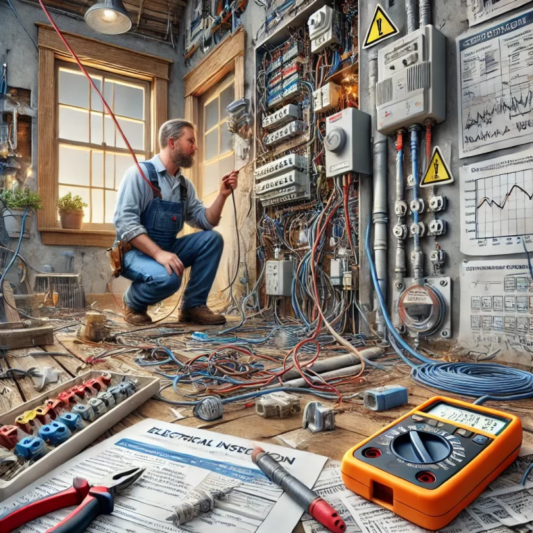
Wiring Process Requirements
1. Verify Wiring Before Connection
Always verify the wiring before making any connections. This helps avoid wiring mistakes and ensures the system functions as intended.
2. Insulation Stripping
When stripping insulation from cables, proceed carefully to avoid damaging the cable cores. Damaging the insulation can lead to electrical leakage or short circuits.
3. Cable to Terminal Connections
Ensure that connections between cables and terminals are secure and uniform. Proper connections are critical to maintaining good electrical conductivity. For multi-strand wires, it’s advisable to use terminal connectors and crimp them securely.
4. Terminal Labeling and Clarity
The terminals within the instrument panels should be clearly labeled according to the design diagrams. The labels should be durable and resistant to fading to ensure that future maintenance and troubleshooting can be done accurately.
5. Terminal Block Installation
Terminal blocks must be securely mounted. If installed at the bottom of a panel, the distance from the base should be at least 250mm; if installed at the top or side, there should be at least 100mm of clearance from the panel’s edges. When installing multiple terminal blocks side by side, ensure that there is a minimum spacing of 200mm between them.

Shielding and Grounding Standards
1. Shield Grounding
The shield of a cable should only be grounded at one side, typically at the control room end. Avoid grounding at both ends, as this could introduce potential differences that might affect performance.
2. Isolation of Intrinsically Safe Circuits
Intrinsically safe circuits should not share the same cable or conduit as regular circuits. To prevent interference, use grounded metal partitions or insulated barriers to maintain a safe distance of at least 50mm between different types of circuits.
3. Identification of Intrinsically Safe Circuits
Intrinsically safe circuits and their components should be marked with blue labels to distinguish them. During installation, ensure that these circuits are isolated to prevent electromagnetic and electrostatic interference that could affect circuit performance.
Additional Precautions
1. Protective Measures
Install protective tubing or a protective cover on the instrument’s entry ports to prevent water ingress. For instruments used outdoors, consider installing protective boxes or wrapping the instruments in nylon plastic bags to avoid damage from moisture or corrosion.
2. Wiring of Compensation Leads
When wiring compensation leads, avoid using terminal lugs (or similar connectors) for connecting dissimilar metals. Using such connectors may cause measurement errors due to unwanted contact between different conductors.
3. Animal Protection
In control rooms, take measures to prevent small animals from damaging wiring. Rodents or other animals can chew through wires, causing short circuits and other electrical issues.
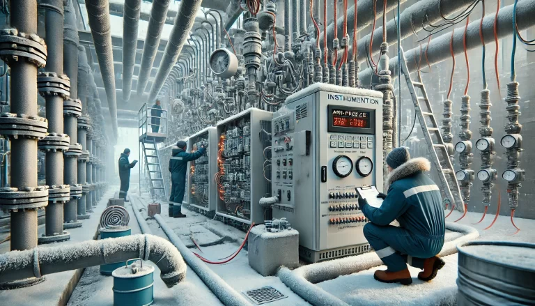
4. Instrument Installation and Commissioning
Before installation, each instrument must undergo individual testing. After installation, conduct a full system check to ensure that the instrument and connected systems operate correctly. During on-site maintenance, it’s essential to communicate closely with technical and process personnel to understand any operational conditions.
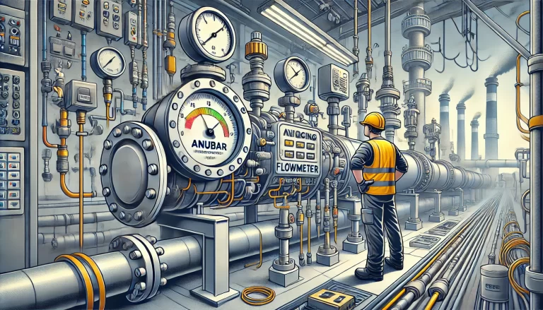
5. Instrument Air Duct Installation
When installing instrument air ducts, position the valve above the centerline of the pipe, ideally at a 90-degree angle to the pipe. This positioning helps prevent debris or contaminants in the air stream from entering the instrument.
6. Surge Protection Installation
In areas susceptible to lightning, install surge protectors in the instrument wiring. Connect the instruments to a surge protector before linking to safety barriers, and ensure that the surge protector and safety barriers are installed on the same side of the wiring system to simplify installation and troubleshooting.
By following these best practices and guidelines, you can ensure that your instrument wiring is safe, reliable, and efficient, minimizing potential errors and improving system performance.