Introduction
Among numerous liquid level measurement instruments, magnetic level gauges are widely used due to their simple structure, convenient installation, reliable measurement, and intuitive display. These gauges find broad application in industries such as petroleum, pharmaceuticals, chemical processing, and wastewater treatment. Among the various installation types, the top-mounted configuration is particularly common. This type of gauge, often installed on the top of containers, is known as the top-mounted magnetic level gauge. It is especially suitable for underground storage tanks, containers where side openings are impractical, and high-viscosity liquid media that are challenging to measure using side-mounted gauges.
Structure and Working Principle
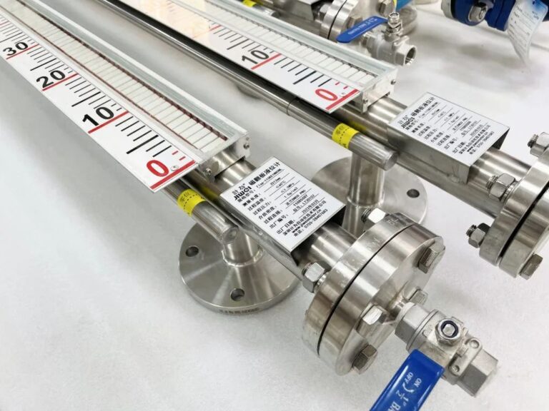
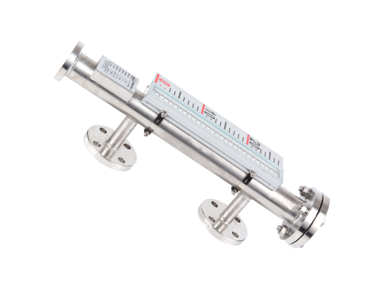
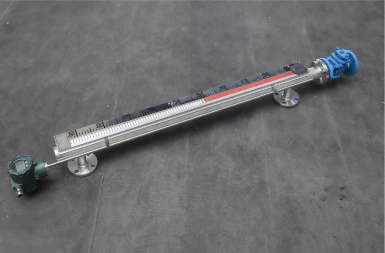
The top-mounted magnetic level gauge comprises two main parts: the upper measurement section and the lower guide tube.
Upper Section: This includes the main measuring tube and a magnetic flip-panel display mounted externally. When the liquid level changes, a magnetic coupling mechanism inside the gauge causes the flip panels to rotate, visually indicating the liquid level. The upper section is typically secured to the top of the container using connection flanges, with sizes ranging from DN80 to DN150.
Lower Section: This portion houses the guide tube where a float moves vertically. The float is magnetically coupled to the upper measuring tube, allowing it to transmit level changes to the display. This design prevents the float from being disrupted by lateral liquid flow, ensuring stable operation.

All magnetic level gauges operate on Archimedes’ principle, where the buoyancy force acting on the float causes it to rise with increasing liquid levels. However, the float begins to rise only when the buoyant force exceeds the float’s total weight. This phenomenon results in a segment of the liquid level, known as the blind zone, where changes are not displayed on the indicator. The length of this blind zone is generally proportional to the size of the float.
Challenges with Blind Zones
The existence of blind zones in top-mounted magnetic level gauges can lead to operational inaccuracies. For instance:
Even when the tank is empty, the indicator may show a residual liquid level due to the initial position of the float.
Misunderstandings about the gauge’s measurement principle may lead to customer dissatisfaction or even failure during project acceptance tests.
To address these issues and enhance the reliability and accuracy of magnetic level gauges, several practical solutions can be implemented.
Solutions to Reduce or Eliminate Blind Zones
1. Precision Manufacturing of Floats
By carefully calibrating the float to match the density of the measured liquid, the length of the float can be minimized. During manufacturing, precise adjustments to the float’s density ensure compatibility with the liquid being measured, thereby reducing the blind zone.
Advantages:
Reduces the length of the blind zone significantly.
Ensures greater accuracy for low liquid levels.
Implementation Example: A chemical plant measuring high-viscosity liquids used customized floats, reducing the blind zone by 20%.

2. Enlarging Flange Specifications
Increasing the flange size (e.g., from DN80 to DN150) expands the diameter of the guide tube. This allows for shorter and wider floats, which in turn decreases the blind zone length.
Advantages:
Reduces blind zone without compromising structural stability.
Improves compatibility with tanks of varying sizes.
Implementation Example: An underground storage facility adopted larger flanges, achieving improved measurement precision in tanks with restricted bottom access.
3. Adjusting Measurement Range
In cases where tanks are not typically emptied completely, or where the bottom liquid levels do not need monitoring, the gauge’s measurement range can be adjusted. By reducing the total range to exclude the blind zone, the issue of false readings when the tank is empty can be eliminated.
Advantages:
Completely eliminates the display of false liquid levels.
Simplifies calibration and usage in practical scenarios.
Implementation Example: A wastewater treatment plant adjusted the range of its magnetic level gauges, eliminating customer complaints about residual readings.

Best Practices for Installation and Maintenance
To ensure optimal performance and longevity of top-mounted magnetic level gauges, the following best practices are recommended:
Correct Selection: Choose the appropriate gauge type based on site-specific requirements and tank characteristics.
Proper Installation: Ensure that flanges and guide tubes are correctly aligned to prevent float disruption.
Routine Maintenance: Regularly inspect and maintain the gauge to address wear and tear, ensuring consistent performance.
Future Directions
While current solutions effectively mitigate blind zones, research into innovative designs, such as new materials and magnetic coupling technologies, could further enhance the accuracy and reliability of magnetic level gauges. Additionally, integrating digital sensors and IoT capabilities may allow for real-time monitoring and predictive maintenance.

Conclusion
The top-mounted magnetic level gauge remains a versatile and reliable instrument for liquid level measurement. By addressing the challenges of blind zones through precision manufacturing, optimized design, and proper maintenance, users can significantly improve measurement accuracy and reliability. As technology continues to evolve, further innovations are expected to enhance the performance and applicability of these instruments across industries.
