Instrument interlock circuit commissioning is a critical process to ensure the safety, reliability, and operational stability of industrial automation systems. This process involves thorough testing and validation of the interlock functions to guarantee they perform as designed under all possible conditions. Below is a detailed guide on the standards and implementation essentials for this process.
I. Standards for Instrument Interlock Circuit Commissioning
Preparation Phase
- Document Review:
- Verify piping and instrumentation diagrams (P&IDs), control logic diagrams, interlock lists, and instrument datasheets.
- Confirm interlock objectives, conditions, and actions (e.g., emergency shutdown requirements).
- Pre-commissioning Check:
- Ensure all instruments (e.g., sensors, transmitters, actuators) are installed correctly, securely fixed, and comply with design specifications.
- Verify cable connections, signal wiring, and power supplies.
- Document Review:
Commissioning Process
- Individual Loop Testing:
- Validate the functionality of individual instruments, ensuring sensors and actuators operate within specified ranges and meet accuracy requirements.
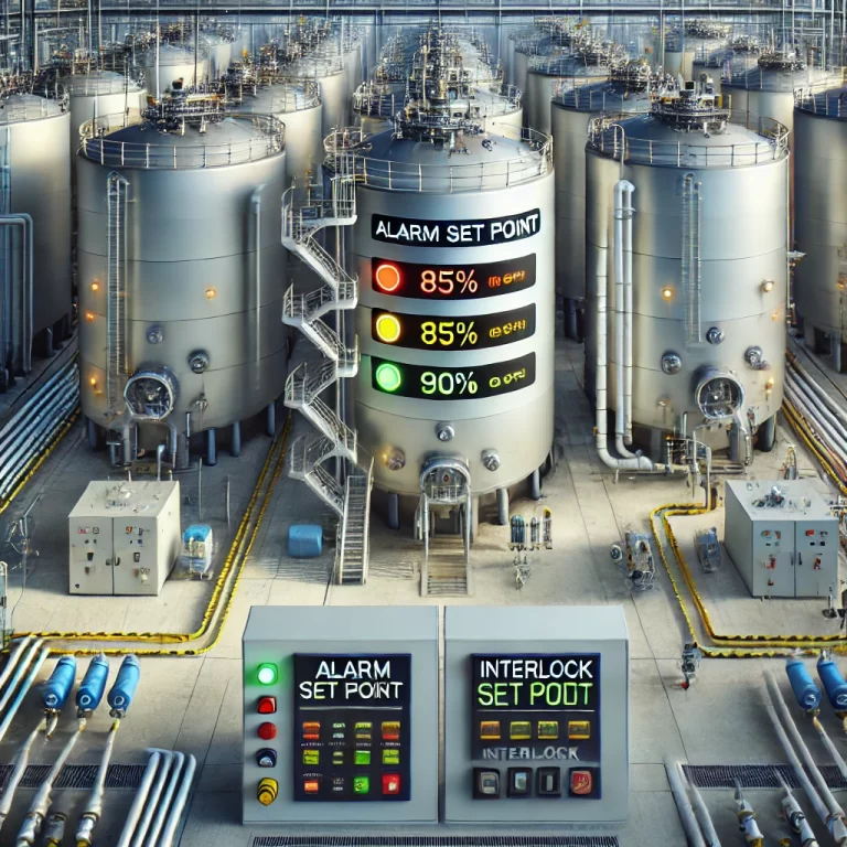
- Verify alarm points, trip setpoints, and signal scaling.
- System-Level Testing:
- Simulate interlock triggering conditions, such as overpressure, high temperature, or low flow, and check the system’s response.
- Ensure signals flow correctly through the Distributed Control System (DCS) or Safety Instrumented System (SIS).
- Dynamic Testing:
- Conduct tests under actual operating conditions by simulating interlock triggers.
- Confirm the system performs the expected shutdown, startup, or control actions without delay or error.
- Failure Simulation:
- Introduce potential failure scenarios, such as sensor disconnections or signal loss, and verify that the system raises alarms or takes appropriate actions.
- Individual Loop Testing:
Required Tools
- Utilize specialized tools such as signal calibrators, loop testers, portable field communicators, and digital multimeters.
- Rely on system-specific software for configuring, monitoring, and testing DCS or SIS.
II. Key Implementation Essentials
Safety Protocols
- Conduct a comprehensive risk assessment before commissioning, identifying potential hazards and preparing mitigation strategies.
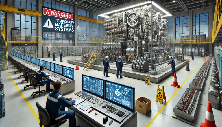
- Ensure strict compliance with safety standards, avoiding unnecessary live testing during active operations.
Verification of Interlock Logic
- Validate all interlock logic conditions to ensure they are consistent with design specifications.
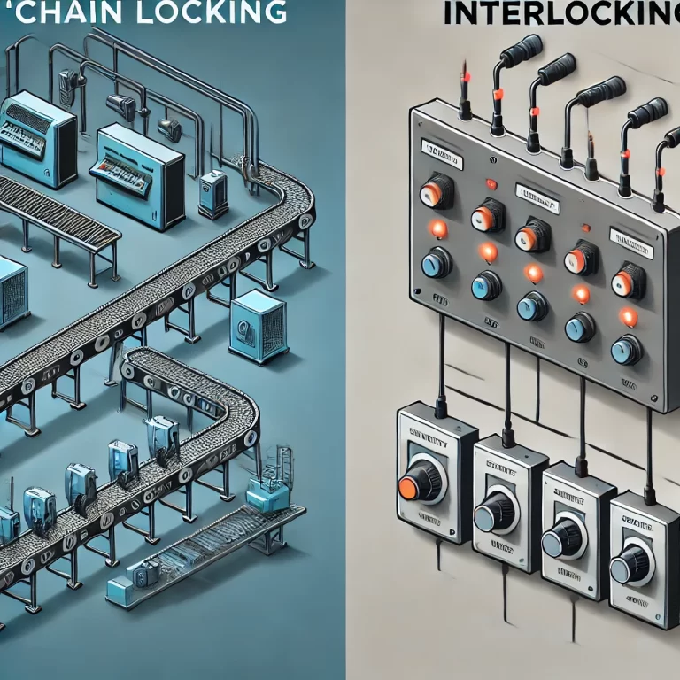
- Check for logical conflicts, ensuring that higher-priority actions override lower-priority ones when required.
Documentation and Records
- Maintain detailed records of every step, including identified issues, parameter adjustments, and test results.
- Create a final commissioning report summarizing the verified interlock functionality and system performance.
Integration Testing
- Conduct integrated tests to ensure the interlock system communicates effectively with other automation components, such as Programmable Logic Controllers (PLCs), Emergency Shutdown Systems (ESDs), and alarms.
- Verify smooth system recovery after interlock deactivation.
Operator Training
- Provide comprehensive training for operators, familiarizing them with interlock logic, system responses, and troubleshooting protocols.
- Supply clear documentation outlining interlock conditions and actions for future reference.
Post-Commissioning Validation
- After commissioning, perform additional checks under normal operating conditions to ensure system stability.
- Schedule periodic reviews to update interlock settings as process requirements change.
III. Common Issues and Their Resolutions
Delayed or Non-Responsive Interlock Actions
- Root Cause: Signal transmission delays, logic programming errors, or mechanical issues in actuators.
- Resolution: Inspect signal pathways, debug interlock logic, and test actuators for responsiveness.
False Alarms or Unintended Trips
- Root Cause: Poor calibration of sensors, overly sensitive alarm thresholds, or incorrect logic configurations.
- Resolution: Recalibrate instruments, fine-tune alarm settings, and validate interlock logic.
Impact on Other Systems During Testing
- Root Cause: Insufficient planning or lack of coordination with ongoing operations.
- Resolution: Clearly define test boundaries and coordinate with operators to minimize disruptions.

Conclusion
Instrument interlock circuit commissioning is a meticulous process requiring adherence to detailed standards and careful execution of key practices. By systematically addressing the preparation, testing, and documentation phases, organizations can ensure interlock systems meet safety and operational requirements. Regular reviews and updates post-commissioning are equally important to maintain system reliability in evolving industrial environments. This structured approach helps prevent accidents, optimize system performance, and build confidence in automated control systems.