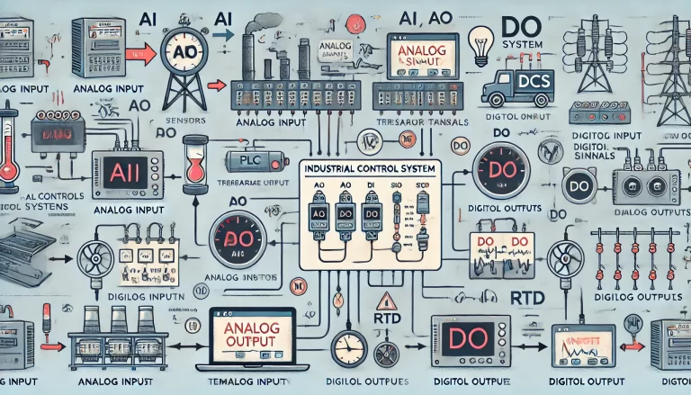
1. AI Signal (Analog Input)
Definition:
AI stands for Analog Input, which refers to continuous signals that represent varying physical quantities in industrial control systems.
Characteristics and Sources:
Analog signals are continuously varying electrical signals, commonly in the form of current (4-20mA) or voltage (0-10V, 1-5V). These signals originate from various field devices, such as:
Temperature sensors (e.g., thermocouples, RTDs) that output voltage or resistance signals corresponding to temperature changes.
Pressure transmitters that output 4-20mA current signals corresponding to varying pressure values.
Flow and level transmitters that provide similar outputs based on process requirements.
Application:
The AI signals are input into control systems such as Distributed Control Systems (DCS) or Programmable Logic Controllers (PLC), where they are converted to meaningful physical values (e.g., temperature, pressure) for process monitoring and control.
Example:
A temperature transmitter in an industrial plant sends a 4-20mA signal to a PLC, which translates it to a temperature range of 0°C to 100°C displayed on the HMI (Human-Machine Interface).
2. AO Signal (Analog Output)
Definition:
AO stands for Analog Output, representing the control system’s ability to send continuous signals to control field devices.
Function and Applications:
AO signals are typically in the 4-20mA or 0-10V range and are used to regulate equipment operations such as:
Speed control in variable frequency drives (VFDs), where a 4-20mA signal determines the motor’s operating frequency.
Valve control in process systems, adjusting valve opening to control flow rate or pressure.
Example:
A DCS system sends an AO signal to a valve actuator, instructing it to open to 50% to regulate the flow of a cooling liquid.

3. DI Signal (Digital Input)
Definition:
DI stands for Digital Input, referring to binary signals that represent discrete states (ON/OFF, TRUE/FALSE, 1/0).
Nature and Purpose:
Digital input signals are used to monitor the status of field devices. These signals can indicate:
Equipment status (e.g., motor running/stopped, breaker open/closed)
Operator actions (e.g., pressing a start/stop button)
Safety interlocks (e.g., emergency stop activation)
Example:
A motor feedback circuit sends a DI signal to the control system indicating whether the motor is running (1) or stopped (0).
4. DO Signal (Digital Output)
Definition:
DO stands for Digital Output, which refers to signals sent from the control system to operate field devices.
Function and Applications:
DO signals are used to control binary operations such as:
Starting and stopping motors via relays or contactors
Opening and closing solenoid valves
Controlling indicator lights for operational feedback
Example:
A PLC sends a DO signal to a solenoid valve to open, allowing compressed air to pass through the system.
5. RTD Signal (Resistance Temperature Detector)
Definition:
RTD is a temperature sensor rather than a signal type, but it produces a variable resistance that correlates with temperature changes.
Working Principle and Characteristics:
RTDs utilize the principle that metal resistance changes with temperature. Common RTDs include:
PT100 sensors, which exhibit 100Ω resistance at 0°C.
RTD signals are typically converted to AI signals (e.g., 4-20mA) via transmitters for use in control systems.
Example:
An RTD sensor in a heat exchanger measures process temperature and provides feedback to a PLC to maintain optimal operating conditions.

Comparison of AI, AO, DI, and DO Signals
| Signal Type | Description | Example Applications | Signal Characteristics |
|---|---|---|---|
| AI | Analog Input | Temperature, Pressure, Flow Measurement | Continuous, 4-20mA, 0-10V |
| AO | Analog Output | Valve, Motor Speed Control | Continuous, 4-20mA, 0-10V |
| DI | Digital Input | Equipment Status Monitoring | Discrete, ON/OFF (1/0) |
| DO | Digital Output | Equipment Control (Start/Stop) | Discrete, ON/OFF (1/0) |
Common Issues and Troubleshooting
AI Signal Issues:
Problem: Signal fluctuations due to electrical noise.
Solution: Use shielded cables and proper grounding.
AO Signal Issues:
Problem: Incorrect control output due to calibration errors.
Solution: Regular calibration and maintenance.
DI Signal Issues:
Problem: False triggering due to contact bounce.
Solution: Use debounce circuits or software filters.
DO Signal Issues:
Problem: Failure to activate due to wiring faults.
Solution: Regular inspection of wiring connections.
Conclusion
Understanding the differences and applications of AI, AO, DI, DO, and RTD signals is essential for the efficient operation of industrial automation systems. Proper implementation and maintenance of these signals ensure accurate process control and monitoring, enhancing overall system performance and reliability.
