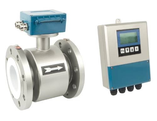
Electromagnetic Flowmeter
Fault Type: Electromagnetic flowmeter indicating lower than actual flow rate.
Instrument Type: Integrated Electromagnetic Flowmeter
Manufacturer and Model: Manufacturer: [To be filled in] Model: [To be filled in] Range: 0-160 m³/h
Operating Conditions: The flowmeter monitors the inlet flow of ash water to the slag lock hopper flushing water tank. It forms a single-loop control system with valve 17FV-2003 to regulate and alarm flow rates, aiming to control the liquid level in the flushing water tank.
Fault Phenomenon: The flow indication is abnormally low, with trend graphs showing a gradual decline over time.
Safety Identification and Precautions Before Operation:
Obtain a maintenance work permit.
Coordinate with the process safety team to isolate the instrument. Set valve 17FV-2003 to manual control.
As the instrument is a four-wire system with a 24VDC supply, disconnect power and confirm disconnection before opening the cover.
If wiring disconnection is necessary, insulate wire ends with electrical tape to prevent short circuits or contact with the instrument housing or pipelines.
Since the medium is ash water, ensure complete drainage before removing the flowmeter. Wear safety goggles, gloves, and protective clothing to prevent splashes.
Seal the meter head securely and waterproof it before removal to protect internal circuits.
Loosen diagonal bolts with a wrench before full removal to check for remaining fluid. Fully remove bolts only after confirming the pipe is empty.
Secure the flowmeter to prevent it from dropping and getting damaged.
Use soft materials to clean scale on the liner to avoid scratches.
Due to high noise near the pump, wear ear protection.
Assign a dedicated safety monitor during the operation.

Fault Analysis and Troubleshooting Approach: Potential causes are categorized into valve issues, flowmeter faults, and process-related problems.
Valve Issues: Blockages may reduce flow. Switch valve 17FV-2003 to manual and adjust the opening. If the flow changes consistently with the valve adjustment, the valve is functioning correctly.
Flowmeter Faults:
Buildup of deposits on the measuring tube’s inner wall.
Damage to the measuring tube lining.
Corrosion of signal connectors.
Process Issues:
Reduced performance of the ash water pump.
Blockages or narrowing of the process pipeline.
Other undefined process issues.
After eliminating valve issues, the focus should shift to the flowmeter and process system. Instrument technicians should prioritize checking their equipment.

Effective Troubleshooting Procedures:
Follow the principle of addressing simpler issues first:
Inspect signal connectors after power disconnection. Check terminals and cables for corrosion. No corrosion found.
Proceed to inspect the measuring tube and liner.
Disconnect power, detach power and signal wires, insulate them with tape, and waterproof the meter head.
Secure the flowmeter with lifting straps to prevent dropping during disassembly.
Verify the pipeline is empty before removal.
Disassembly revealed significant deposits inside the measuring tube, causing measurement inaccuracies.
Clean the inner wall with a soft cloth and water, avoiding liner and electrode damage.
Reinstall the flowmeter after confirming the liner is intact.
Restore the system and verify normal operation.
Preventive Measures and Improvements:
Due to the ash water medium’s tendency to accumulate impurities, proactively anticipate possible faults.
Schedule regular maintenance to inspect and clean the measuring tube to ensure accurate readings.

10. Fault Handling Experience: Flowmeter faults can be cross-verified by monitoring the slag lock hopper flushing water tank’s refill time. Comparing refill durations during normal and abnormal flowmeter readings can help determine if the issue lies within the flowmeter or the process system. If refill times remain similar, the valve and process system are likely functioning correctly, confirming a flowmeter fault. Conversely, increased refill times suggest other potential causes requiring further investigation.
This detailed procedure ensures comprehensive troubleshooting and maintenance of the electromagnetic flowmeter, improving operational reliability and accuracy.
