Distributed Control Systems (DCS) are critical in industrial automation, used extensively in industries such as petrochemical, power generation, and chemical manufacturing. DCS configuration, often referred to as “DCS setup” or “DCS engineering,” involves tailoring the system to meet specific process control and operational requirements. This article provides a comprehensive guide to understanding and executing DCS configuration with an example of a boiler control system.
What is DCS Configuration?
DCS configuration is the process of setting up a DCS to control and monitor industrial processes. It encompasses:
- Hardware configuration: Setting up controllers, I/O modules, and network connections.
- Software configuration: Defining control logic, alarms, and human-machine interface (HMI) displays.
- Communication setup: Integrating the DCS with other systems or equipment using communication protocols.
- Testing and optimization: Ensuring that the system performs correctly in real-world scenarios.
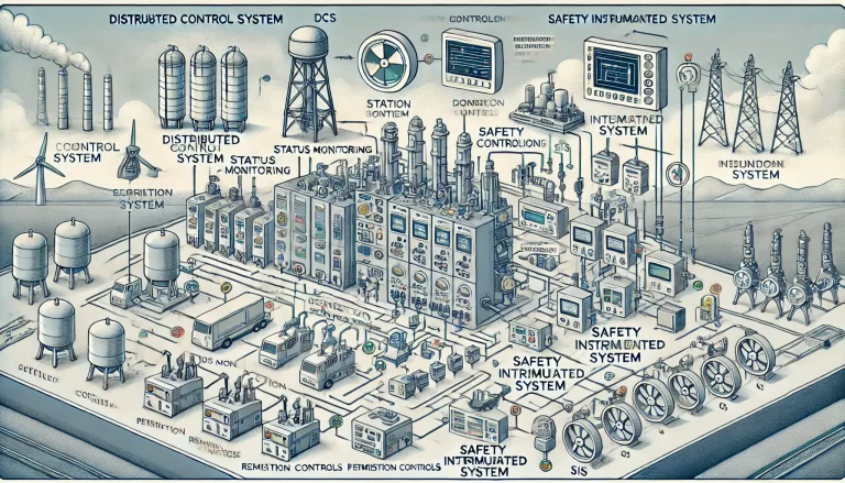
Core Components of DCS Configuration
1. Hardware Configuration
- Controllers and Modules: Assign specific controllers for process areas and configure input/output (I/O) modules for signal processing. Examples include analog input (AI) modules for temperature sensors and digital output (DO) modules for valves.
- Redundancy: Define redundant controllers or networks to enhance reliability.
- Field Devices Integration: Connect field devices such as sensors and actuators to the appropriate I/O modules.
- Power Supply and Network Setup: Ensure power redundancy and configure Ethernet or proprietary communication networks for data flow.
2. Logic Programming
DCS systems use function block diagrams (FBD), ladder logic, sequential function charts (SFC), or structured text for programming.
- Control Logic:
- Develop algorithms for process control, such as Proportional-Integral-Derivative (PID) controllers.
- Example: Configure a PID block to maintain boiler pressure within desired limits.
- Interlock Logic:
- Define safety conditions. For instance, stop the boiler if water levels are critically low.
- Sequential Control:
- Create start-up or shutdown sequences. For a boiler, this might involve checking prerequisites (e.g., water levels and pressure) before firing the burner.
3. HMI Configuration
Human-Machine Interface (HMI) is vital for operators to interact with the DCS.
- Graphical Displays:
- Design process mimic diagrams with real-time status indicators for equipment and instruments.
- Trends:
- Configure historical and real-time trends for key variables, such as boiler temperature and water level.
- Alarm Management:
- Set up alarms for abnormal conditions, categorized by priority levels (e.g., high, medium, low).
- Control Panels:
- Create user-friendly panels with buttons and sliders for manual overrides.
4. Parameter Setup
Each control block requires fine-tuning for optimal performance.
- PID Parameters:
- Adjust proportional gain, integral time, and derivative time based on the process dynamics.
- Example for boiler temperature control:
- Proportional gain: 1.5
- Integral time: 10 seconds
- Derivative time: 1 second
- Alarm Thresholds:
- Define acceptable operating ranges. For example:
- Boiler pressure: 0.8–1.2 MPa (normal)
- Low-pressure alarm: <0.8 MPa
- High-pressure alarm: >1.2 MPa
- Define acceptable operating ranges. For example:
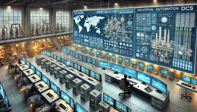
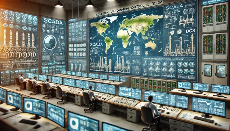
5. Communication Configuration
Modern DCS systems need to communicate with other systems, such as Programmable Logic Controllers (PLCs), Supervisory Control and Data Acquisition (SCADA), or third-party devices.
- Protocols:
- Configure Modbus, OPC, or proprietary protocols for data exchange.
- Data Mapping:
- Assign specific registers for data transfer. For instance, map temperature sensor data to a specific address.
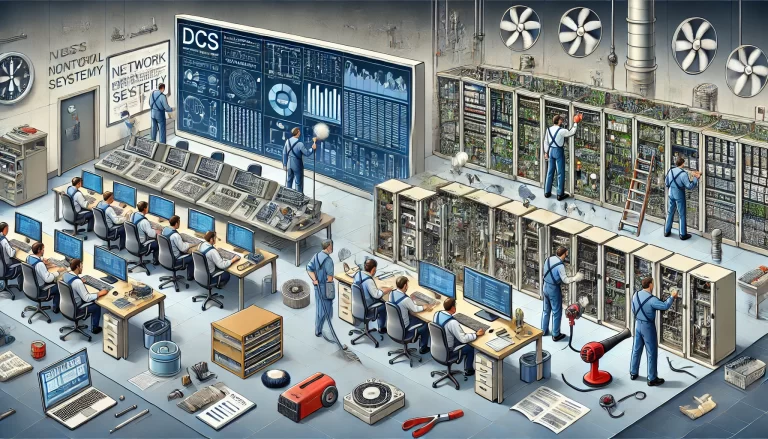
6. Testing and Optimization
Before deploying the system, rigorous testing is essential.
- Signal Loop Checks:
- Verify that sensor signals are correctly received and actuators respond as expected.
- Logic Testing:
- Simulate process conditions to test interlocks and control logic.
- HMI Validation:
- Ensure that displays and alarms function as intended.
- Optimization:
- Fine-tune parameters based on real-time observations during commissioning.
Example: Boiler Control System DCS Configuration
Scenario: Configure a DCS for an industrial boiler to control pressure, temperature, and water level.
Step 1: Hardware Setup
- Connect a pressure sensor (4-20 mA) to an analog input module.
- Connect a burner control valve to an analog output module.
- Assign digital outputs for water pump on/off control.
Step 2: Logic Programming
- Implement PID control for:
- Pressure control: Adjust burner valve position.
- Water level control: Start/stop the water pump.
- Add interlock logic:
- Shutdown the burner if water level falls below a critical threshold.
Step 3: HMI Design
- Create a graphical display showing:
- Real-time pressure, temperature, and water level.
- Control buttons for manual start/stop.
- Add alarms for:
- Low water level
- High pressure
Step 4: Parameter Tuning
- Set pressure control PID parameters:
- Proportional gain: 2.0
- Integral time: 5 seconds
- Derivative time: 0.5 seconds
- Define alarm thresholds:
- Pressure: High: >1.5 MPa; Low: <0.7 MPa
Step 5: Testing
- Perform loop checks to validate sensor and actuator wiring.
- Simulate operational scenarios (e.g., high pressure) to verify interlocks.
Conclusion
DCS configuration is a detailed and methodical process requiring in-depth knowledge of both the system and the industrial process it supports. Properly configured DCS systems enhance process efficiency, ensure safety, and provide operators with the tools needed to manage complex operations effectively. With advancements in DCS technology, such as integration with IoT and AI, the scope and impact of DCS configuration continue to grow, offering even greater value to industrial automation.