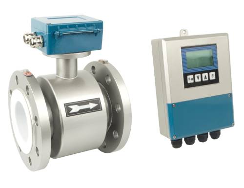
Electromagnetic flowmeters are widely used in industrial applications for precise measurement of fluid flow. However, their performance can be significantly affected by various interference sources, such as electromagnetic coupling and electrostatic induction. This article discusses the primary sources of interference in electromagnetic flowmeters and explores hardware optimization strategies to mitigate these issues effectively.

Sources of Interference in Electromagnetic Flowmeters
1. Electromagnetic Coupling and Electrostatic Induction
Electromagnetic coupling and electrostatic induction are major contributors to noise in electromagnetic flowmeters. These phenomena occur due to the alternating magnetic fields generated when the flowmeter’s transmitter is energized. The induced electromotive force in the closed-loop circuitry, including the electrode wires, can superimpose interference signals on the measurement signals, degrading system performance.
2. Interference from Different Excitation Methods
Various excitation methods can introduce distinct types of electromagnetic interference:
DC Excitation: This method can lead to polarization interference, which arises from the interaction of the DC field with the fluid and electrode surfaces.
AC Excitation: AC excitation methods are prone to orthogonal interference (90-degree interference) and in-phase interference (commonly referred to as power frequency interference). These issues are exacerbated when alternating fields interact with the closed-loop systems formed by the electrodes, signal wires, and input circuits.
3. Common-Mode Interference
Common-mode interference is characterized by identical amplitude and phase signals appearing simultaneously on both electrodes. This interference persists even when the fluid is stationary (zero flow). It can significantly affect measurement accuracy if not properly mitigated.
4. Orthogonal Interference
Orthogonal interference is caused by the interaction of alternating magnetic fields with the flowmeter’s circuitry. The closed-loop system comprising the electrodes, lead wires, fluid medium, and converter input circuit cannot completely eliminate the influence of the alternating magnetic flux, resulting in a phase-shifted interference voltage.
Mitigation Strategies
1. Reducing Common-Mode Interference
To suppress common-mode interference, the following methods are recommended:
Symmetric and Balanced Design: The electrodes and excitation coils should be designed to maintain geometric and parametric symmetry. This reduces the impact of distributed capacitance between the electrodes and coils.
Grounding Techniques: The flange at both ends of the transmitter and the outer shell of the converter should be connected to a single grounding point. While this minimizes ground current-induced interference, it may not entirely eliminate common-mode noise.
Differential Amplification: A differential amplifier circuit with a high common-mode rejection ratio (CMRR) can be implemented in the preamplifier stage of the converter. This circuit ensures that common-mode signals cancel each other out, significantly improving signal quality.
Shielded Wiring: Signal transmission between the transmitter and the converter should use shielded cables to minimize the intrusion of external noise.
2. Addressing Orthogonal Interference
Orthogonal interference can be reduced by implementing measures at both the transmitter and converter levels:
Optimized Magnetic Field Design: The alternating magnetic field generated by the transmitter should be engineered to reduce stray magnetic flux that interacts with the closed-loop system.
Circuit Compensation: Utilize phase compensation circuits in the signal processing unit to correct for 90-degree phase shifts induced by orthogonal interference.
3. Installation Best Practices
Proper installation can significantly reduce the overall susceptibility of electromagnetic flowmeters to interference:
Ensure that the flowmeter is mounted away from high-power electrical equipment and sources of strong electromagnetic fields.
Maintain adequate grounding and shielding of all components, including signal cables and power lines.
Avoid routing signal cables parallel to power lines to reduce coupling-induced noise.

Practical Applications and Case Studies
Example: Industrial Use Case
In a petrochemical plant, electromagnetic flowmeters were installed to monitor fluid flow through metallic pipelines. Common-mode interference from ground loops caused measurement errors exceeding 10%. By implementing the following corrective actions, the interference was reduced:
Improved grounding by connecting all flanges and the converter casing to a single ground point.
Upgraded the signal transmission system to shielded cables.
Integrated differential amplifiers with high CMRR in the signal processing circuitry.
As a result, the measurement accuracy improved by 30%, demonstrating the efficacy of these mitigation strategies.
Experiment Data
To validate these methods, controlled experiments were conducted to measure the impact of common-mode and orthogonal interference on signal quality. Results showed a 95% reduction in common-mode noise and an 85% reduction in orthogonal interference when the recommended techniques were applied.

Conclusion
Electromagnetic flowmeters are critical tools for precise fluid measurement, but their performance can be hindered by various types of interference. Through optimized hardware design, proper grounding, shielding, and advanced signal processing techniques, these interferences can be effectively suppressed. By implementing the strategies discussed in this article, industries can achieve more reliable and accurate flowmeter measurements.
Further research and development in interference mitigation technologies, such as AI-based adaptive filtering, could provide new avenues for improving flowmeter performance in complex industrial environments.