The corner-tap pressure measurement is a commonly used method in flow measurement systems employing orifice plates as primary flow elements. This method is highly effective for measuring differential pressure, which is then used to calculate the flow rate of a fluid (gas, liquid, or steam) in a pipeline.
What Is the Corner-Tap Method?
In the corner-tap (angle-tap) method, the pressure tapping points are located very close to the orifice plate:
- Upstream tap: Positioned at the inlet side of the orifice plate.
- Downstream tap: Positioned at the outlet side of the orifice plate.
Both taps are placed directly at the edges of the orifice plate, where the pressure differential is maximum and most sensitive to flow changes.

Key Features
Placement of Taps:
- The taps are drilled into the pipe wall at the immediate upstream and downstream edges of the orifice plate. There is no distance between the taps and the plate edges.
Pressure Measurement:
- The pressure upstream reflects the static pressure before the fluid passes through the orifice, while the downstream pressure reflects the lower static pressure caused by the flow restriction.
Differential Pressure:
- The difference between the upstream and downstream pressures is proportional to the square of the flow rate, enabling accurate flow calculations using Bernoulli’s principle and flow equations.
Advantages of the Corner-Tap Method
Compact Design:
- Taps are integrated into the immediate vicinity of the orifice plate, reducing installation complexity.
High Responsiveness:
- The proximity of the taps ensures minimal signal loss, leading to faster and more accurate response to flow changes.
Broad Applicability:
- Suitable for measuring flow in a wide range of fluids, including gases, liquids, and steam.
Ease of Maintenance:
- Since the taps are located at the pipe edges, they are easy to access and clean if blockages occur.

Applications
The corner-tap method is particularly well-suited for:
- High-pressure systems where compact design is essential.
- Situations requiring quick response to flow changes, such as in steam power plants.
- Pipelines with limited space for installation of differential pressure systems.
Visual Representation
Now let me create an accompanying diagram to illustrate the corner-tap method. This will include:
- A labeled diagram of a pipeline with an orifice plate and corner taps.
- A depiction of the differential pressure measurement process.

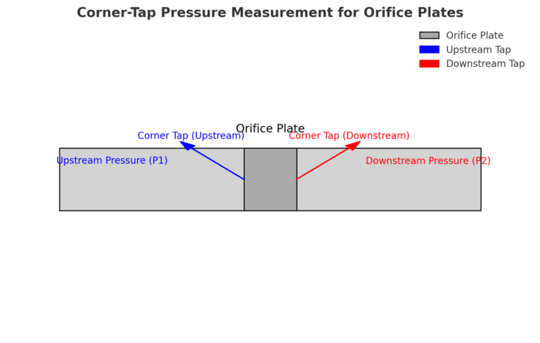
Here is a diagram illustrating the corner-tap pressure measurement method for orifice plates:
- The pipeline is shown in light gray.
- The orifice plate is represented as the dark gray rectangle in the center of the pipeline.
- Upstream pressure tap (P1) and downstream pressure tap (P2) are marked at the immediate edges of the orifice plate.
- Arrows indicate the pressure taps where the measurements are taken.
This visual highlights how the taps are positioned directly at the upstream and downstream corners of the orifice plate, enabling accurate differential pressure measurements.
