Instrument tag numbers, often referred to simply as tag numbers, are unique identifiers assigned to instruments and devices used in industrial processes. They play a crucial role in system design, implementation, and maintenance by providing a consistent and logical means of identifying and referencing instruments in technical documentation, control systems, and field operations.
Components of an Instrument Tag Number
Instrument tag numbers typically follow a structured format defined by standards such as ISA S5.1 (Instrumentation Symbols and Identification) or internal company conventions. The structure often includes the following elements:
1. Functional Identifier (Prefix)
The prefix denotes the physical parameter or function being measured or controlled. Common functional identifiers include:
T: Temperature
P: Pressure
F: Flow
L: Level
A: Analysis
H: Hand-operated device
Examples:
T for a temperature transmitter.
P for a pressure indicator.
2. Loop or Point Number
The point number is a unique numeric value assigned to distinguish between multiple instruments serving similar purposes. This is often a three-digit number, such as 101, 102, etc.
3. Suffix (Optional)
The suffix provides additional details about the instrument’s specific function or output type. Common suffixes include:
I: Indicator (provides a direct readout)
R: Recorder (logs data)
C: Controller (regulates a parameter)
T: Transmitter (sends signals to other devices)
S: Switch (binary state control)
4. Modifiers (Optional)
In some systems, additional characters or abbreviations may be appended to specify attributes such as:
Signal type (e.g., pneumatic or electronic).
Control mode (e.g., automatic or manual).
Process unit or plant section.
Example Tag Numbers and Their Interpretation
PIT-101
P: Pressure
I: Indicator
T: Transmitter
101: Unique loop number
Interpretation: A pressure transmitter with an indicator, used in process loop 101.
LIC-102
L: Level
I: Indicator
C: Controller
102: Unique loop number
Interpretation: A level controller with indication for process loop 102.
FT-202
F: Flow
T: Transmitter
202: Unique loop number
Interpretation: A flow transmitter in process loop 202.
Standards Governing Instrument Tag Numbers
ISA S5.1 Standard
The International Society of Automation (ISA) has established guidelines to ensure consistent and standardized identification of instruments across industries. The ISA S5.1 Standard specifies rules for tag number formatting, instrument symbols, and abbreviations to facilitate clear communication.
ISO 14617-6
The International Organization for Standardization (ISO) also provides guidelines for graphical symbols used in process control systems, including tag identification.
Applications of Instrument Tag Numbers
1. Engineering Design
During the engineering and construction of industrial plants, tag numbers are used extensively in Piping and Instrumentation Diagrams (P&IDs), equipment layouts, and wiring diagrams. They help engineers and designers document the relationship between instruments and the processes they monitor or control.
2. Control Systems
Tag numbers are integral to control systems such as Distributed Control Systems (DCS) and Programmable Logic Controllers (PLC). Each tag number corresponds to a specific signal or control loop, enabling operators to monitor and adjust process parameters.
3. Maintenance and Troubleshooting
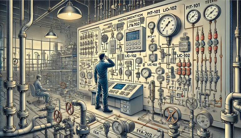
Maintenance teams rely on tag numbers to locate and identify instruments in the field quickly. For example, when troubleshooting a pressure drop in a pipeline, a technician can refer to the pressure transmitter identified as PIT-101 to examine its readings or calibration.
4. Operational Monitoring
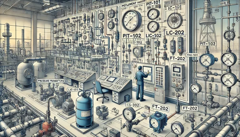
In control rooms, tag numbers are displayed on Human-Machine Interfaces (HMIs) and SCADA systems, allowing operators to monitor real-time process data and take corrective actions as needed.
Common Challenges and Best Practices
Challenges:
Non-Standardized Tagging: Inconsistent or non-standardized tag numbers can lead to confusion, especially in large facilities or when integrating systems from multiple vendors.
Obsolete Documentation: Over time, undocumented changes to tag numbers or their associated devices can create discrepancies between field equipment and control system records.
Best Practices:
Adopt a Standard: Use established standards such as ISA S5.1 or ISO 14617-6 to ensure consistency across projects.
Maintain Documentation: Regularly update P&IDs, control logic diagrams, and asset databases to reflect changes.
Use Descriptive Tags: While brevity is important, include enough detail in the tag structure to avoid ambiguity.
Conclusion
Instrument tag numbers are the backbone of efficient process control and maintenance in industrial settings. They provide a standardized way to identify, reference, and manage instruments, ensuring smooth operation, effective communication, and rapid troubleshooting. Understanding their structure and applications is essential for engineers, operators, and maintenance personnel involved in industrial automation.