Electrical diagrams are essential tools for designing, troubleshooting, and understanding electrical systems. Wires, as fundamental components, are represented with specific symbols and conventions to ensure clarity and uniformity. Here, we will explore the detailed methods of representing wires in electrical diagrams.
1. Basic Representation of Wires
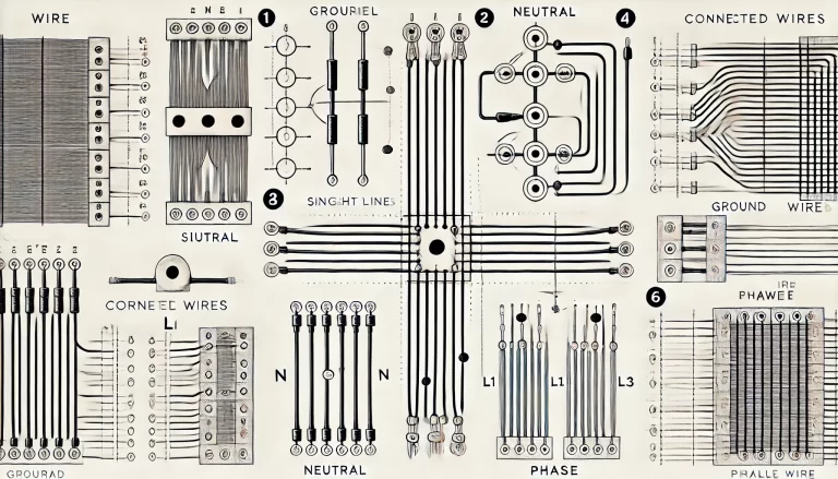
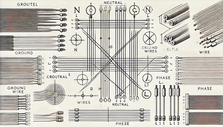
Single Wire
- Symbol: A single line represents a wire connecting two points in a circuit. It is drawn as a straight or curved line.
- Function: Indicates the electrical connection between two components.
Crossing Wires
Wires may cross paths in a circuit, and it is crucial to differentiate between connected and unconnected crossings:
- Not Connected: When two wires cross but do not form an electrical connection, they are drawn as intersecting lines without any additional markings.
- Connected: If wires are electrically connected at the crossing, a small dot, known as a “node” or “connection point,” is added at the intersection.
Parallel Wires
- When multiple wires run in parallel, they are represented as several straight lines placed closely together. Each line corresponds to an individual conductor.
2. Wire Terminals and Endpoints
Labeling
- The endpoints of wires are often labeled to indicate the terminal or component they connect to.
- Labels may include terminal numbers, letters, or symbols for easy identification.
Breaks and Continuations
- If a wire spans multiple sections of a diagram, its path may be broken. In such cases:
- Labels (such as numbers or letters) are added at the break points to indicate continuity.
- A reference note may specify where the wire continues in the diagram.
3. Special Types of Wires
Ground Wires
- Symbol: A grounding wire is represented with a standard grounding symbol: three lines of decreasing length stacked vertically, resembling an inverted triangle.
- Purpose: Indicates a connection to the ground or a reference potential.
Neutral Wires
- Representation: Neutral wires are often labeled “N” to distinguish them from live wires.
- Purpose: Represents the return path in AC systems.
Phase (Live) Wires
- Phase wires are labeled as “L1,” “L2,” and “L3” in three-phase systems to indicate the specific phase.
Control and Signal Wires
- These are sometimes represented with dashed or dotted lines to differentiate them from power wires.
4. Wire Colors and Coding
In physical wiring, color coding is used to distinguish wires:
- Live Wires: Typically red, yellow, or blue for three-phase systems.
- Neutral Wire: Light blue in many international standards.
- Ground Wire: Green with yellow stripes or plain green.
Color codes vary by country and standard (e.g., IEC, NEC).
5. Standards and Notations
The representation of wires follows specific international and national standards to ensure uniformity. Key standards include:
- IEC (International Electrotechnical Commission): Defines universal symbols and conventions.
- ANSI/IEEE (American National Standards Institute/Institute of Electrical and Electronics Engineers): Commonly used in the United States.
- GB/T (China National Standards): Aligns closely with IEC standards but may include localized adjustments.
6. Practical Considerations in Diagram Design
- Clarity: Wires should be drawn clearly and spaced appropriately to avoid confusion.
- Annotation: Wires must be annotated with details such as wire numbers, types, or terminal IDs to facilitate troubleshooting.
- Simplicity: Complex diagrams often use simplified representations or references to focus on key circuit elements.
Conclusion
Wires are the backbone of any electrical circuit, and their representation in diagrams is foundational for understanding and constructing systems. By adhering to standard conventions—such as using clear symbols, distinguishing connections, and applying appropriate annotations—engineers and technicians can create effective and universally comprehensible electrical diagrams.