In industrial settings, electrical and instrumentation (E&I) cable trays or bridge racks play a critical role in organizing and supporting power, control, and signal cables across facilities. An effective layout ensures safety, minimizes interference, reduces maintenance time, and keeps the overall system organized. Below are the key principles to guide the layout of E&I cable trays, focusing on practical, safety, and efficiency aspects.
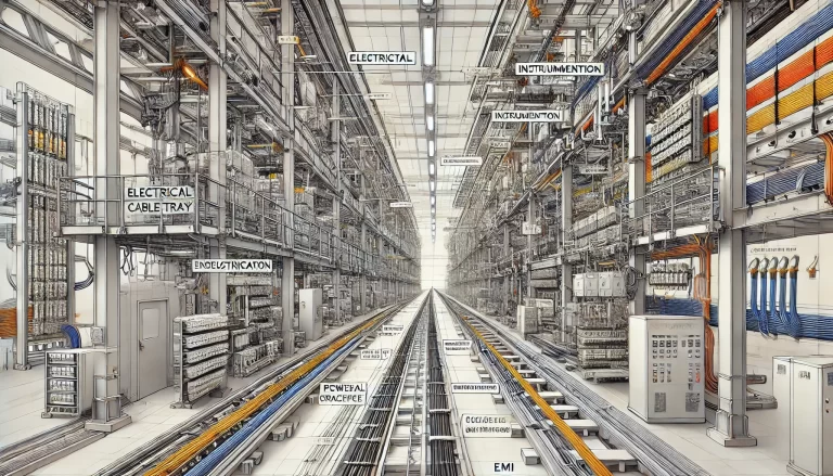
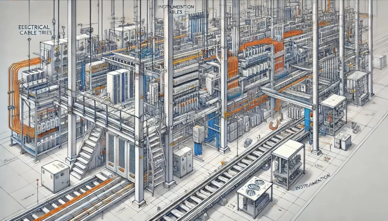
1. Separation of Electrical and Instrumentation Cables
Electrical on Top, Instrumentation Below: Typically, electrical trays are positioned above instrumentation trays. This arrangement minimizes potential electromagnetic interference (EMI) that power cables might cause to sensitive instrumentation and control cables below.
Layered Separation: Strong current and high-voltage cables are positioned apart from low-current, low-voltage instrumentation cables. Layered separation reduces interference, preserving the quality of signal transmission for instrumentation and control systems.
2. Minimum Spacing and Segregation
Spacing Standards: Electrical (power) and instrumentation (signal/control) cable trays should maintain a minimum vertical and horizontal distance. Industry standards often recommend at least 300mm (12 inches) of spacing between power and control trays to minimize EMI.
Dividers or Partitions: Where cables must be close due to space constraints, using a metal partition between power and control trays can help prevent interference. This is particularly important in areas with dense cabling or high electromagnetic field (EMF) environments.
3. Optimal Path and Route Planning
Straightforward Pathways: Cable trays should follow the shortest practical route between equipment, minimizing the need for unnecessary bends and junctions. Reducing cable length decreases material costs and minimizes power loss over long distances.
Avoiding Crossovers and Congestion: If trays must intersect, use multi-level layouts or bridges to avoid physical cable crossovers. This reduces cable wear and makes individual cable trays easier to access for repairs and upgrades.
Service Access: Layouts should allow easy access to cables for routine maintenance or troubleshooting. Avoid trays positioned too close to obstructions like pipes, structural columns, or ventilation ducts.
4. Consideration of Environmental Factors
Heat Dissipation: Power cables generate heat, which needs adequate ventilation for safety and longevity. Allow air gaps between trays to enable heat dissipation, especially for high-voltage cables.
Humidity and Temperature Resistance: In humid or high-temperature environments, consider using trays made of materials resistant to corrosion, such as stainless steel or coated aluminum, and provide additional spacing to prevent overheating.
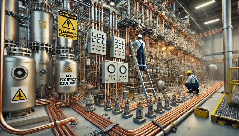
Hazardous Zones: In areas where the risk of sparks or fire is high, such as near combustible materials, additional fireproofing measures (such as fire-retardant trays or coatings) are essential.
5. Load and Support Planning
Weight Distribution: The trays must be designed to support the total weight of the cables they carry, including future load expansions. This ensures the trays won’t sag or fail under the weight of new cables added over time.
Regular Support Spacing: Install support brackets at regular intervals (e.g., every 1.5 meters or 5 feet) to ensure stability, particularly for long horizontal runs.
6. Safety and Compliance with Standards
Electrical Safety Standards: Ensure compliance with local and international standards such as the NEC (National Electrical Code) or IEC (International Electrotechnical Commission) guidelines. This includes tray spacing, grounding requirements, and protection measures.
Overload Prevention: Avoid overloading trays with too many cables, which can lead to overheating, cable damage, and safety risks. Calculate the tray’s load capacity based on the total cable weight and volume and adhere to safety margins.
Grounding and Bonding: Metal cable trays often require grounding to prevent electrical shock hazards. Ensure proper bonding and grounding at each tray connection.
7. Aesthetic and Organizational Considerations
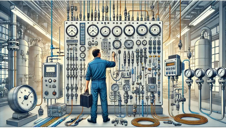
Labeling and Color Coding: Labeling trays and cables helps identify different circuit types (power, control, instrumentation) and their destination. Color-coding can improve identification, especially in complex installations with multiple trays.
Clean and Organized Layouts: While aesthetics might seem secondary, a well-organized cable tray layout can significantly improve maintenance efficiency. Organized layouts reduce the risk of accidental damage or entanglement, which can occur when cables are cramped or unplanned.
8. Future Expandability
Additional Capacity: When designing the tray layout, consider future needs for additional cables. Providing some extra space can save costs in the long run, allowing easy upgrades without needing to replace the entire tray system.
Modular Design: Modular tray systems allow for easy expansion by adding new segments or layers without overhauling the existing infrastructure.
Conclusion
By adhering to these principles, E&I cable tray layouts can achieve the essential balance of safety, efficiency, and durability. A well-planned layout not only meets present requirements but also adapts to future demands, ensuring both system reliability and ease of maintenance.