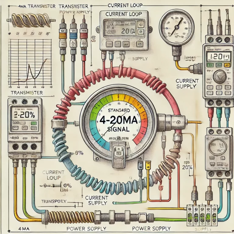
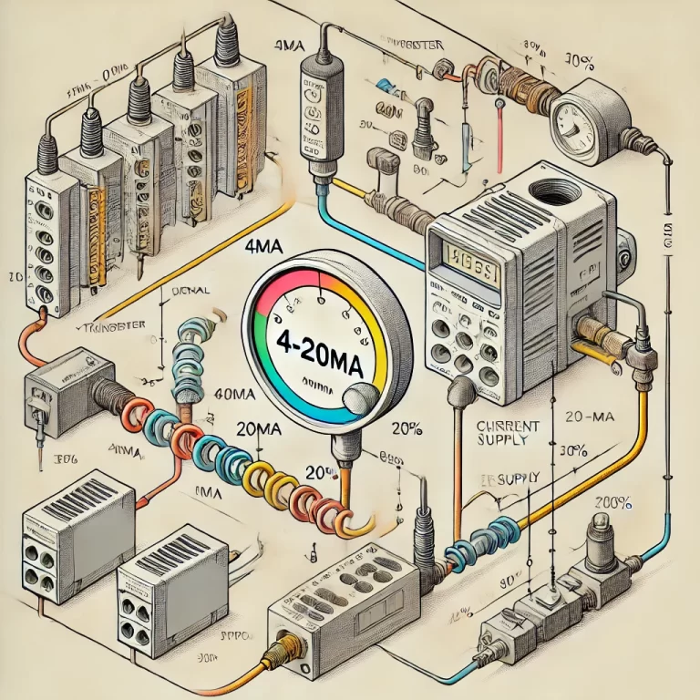
The 4-20mA current loop is a widely used standard in industrial control and instrumentation systems, primarily for transmitting analog signals over long distances. It is valued for its simplicity, reliability, and immunity to electrical noise. However, one of the most frequent questions engineers and technicians encounter is: How far can a 4-20mA signal be transmitted? The answer to this depends on several key factors. Let’s break them down in detail:

1. Wire Resistance
Wire resistance plays a significant role in determining how far a 4-20mA signal can travel. Longer transmission distances introduce higher resistance in the wire, which can cause voltage drops and signal degradation.
- Wire Gauge (AWG): Thicker wires (with a lower American Wire Gauge number) have less resistance, allowing for longer transmission distances. For instance, 18 AWG wire has a lower resistance per meter compared to 24 AWG wire, making it more suitable for long-distance signal transmission.
- Resistance Per Length: Different materials have different resistances. Copper wire is commonly used for 4-20mA loops due to its relatively low resistance. As a general guideline, higher resistance means shorter transmission distances unless other factors (such as increased power supply voltage) are considered.
2. Power Supply Voltage
The supply voltage in a 4-20mA loop must be high enough to overcome the resistance of the wire and the load (such as a transmitter, sensor, or controller) without dropping below the necessary operational voltage.
- Standard Voltage Levels: A typical 4-20mA current loop operates on 24V DC, but loops can function with voltages ranging from 12V to 36V. If the loop experiences significant voltage drop due to long distances or high resistance, increasing the power supply voltage is often necessary to ensure proper operation. For example, increasing the supply to 36V can help maintain a stable signal over a longer distance.
- Voltage Drop Calculations: The voltage drop across the loop is proportional to the total resistance (wire plus load) and the current. Ensuring that there is still sufficient voltage at the end of the loop (after all losses) is critical for maintaining signal integrity.
3. Total Load Resistance
The total load resistance within the current loop, including the resistance of all connected devices (such as transmitters, controllers, sensors, and cables), affects the maximum transmission distance. As resistance increases, the voltage drop across the loop increases.
- Loop Impedance: Each device in the loop contributes to the overall impedance. If the total impedance (load + wire resistance) becomes too high, the voltage available to power the devices may be insufficient, leading to signal loss or distortion.
- Low-Resistance Loads: For long-distance applications, minimizing the number of high-resistance components or choosing low-impedance devices can help maintain the signal over greater distances.
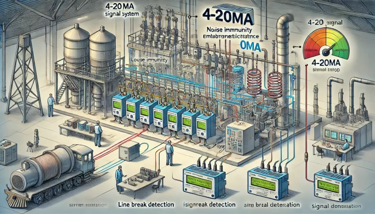
4. Environmental Factors and Interference
Electromagnetic interference (EMI) and radio frequency interference (RFI) are common concerns in industrial environments, particularly when long-distance wiring is involved. EMI can distort signals and cause inaccuracies.
- Shielded Cables: To minimize interference, shielded cables are typically used for long-distance 4-20mA transmission. The shield, often a metal mesh or foil wrapping, blocks external interference from affecting the signal.
- Twisted-Pair Cables: Twisting the wires together helps cancel out noise that may be induced along the length of the cable. This is particularly useful in noisy industrial environments where motors, transformers, or other sources of EMI are present.
- Grounding: Proper grounding of the shield and the loop can also mitigate interference and ensure signal accuracy over long distances.
5. Signal Amplifiers and Repeaters
In some cases, if the distance becomes too long or the signal weakens due to resistance and load, signal amplifiers or repeaters can be introduced into the loop. These devices amplify the signal and enable it to travel further without significant loss.
- Boosting Signal Integrity: Signal repeaters can regenerate the 4-20mA signal at various points along the loop to ensure that the signal remains strong over very long distances.
- Cost vs. Distance: While signal amplification adds cost and complexity to the system, it can be essential in situations where the signal must be transmitted over distances of more than 1,000 meters.

Typical Transmission Distances
Under normal conditions, a 4-20mA signal can typically travel between 200 to 1000 meters (656 to 3280 feet) without major issues. However, in optimized conditions with low resistance wires, higher supply voltage, and proper shielding, the signal can travel over 1,500 meters (4,921 feet). Conversely, in environments with significant interference or where thinner wires are used, the effective transmission distance might be shorter.
Example Calculation for Transmission Distance
Let’s consider an example where a 4-20mA signal is transmitted using a 24V DC power supply over a distance of 500 meters using 18 AWG copper wire. The wire resistance per meter for 18 AWG copper wire is approximately 0.021 ohms.
- Wire Resistance: For 500 meters of wire, the total wire resistance would be 0.021 Ω/m×500 m=10.5.
- Load Resistance: If the total load resistance (including the sensor and receiver) is 250 ohms, the total loop resistance would be 250 Ω+10.5 Ω=260.5 .
- Voltage Drop: At 20mA (the maximum current), the voltage drop across the loop would be 20 mA×260.5 Ω=5.21 V.
In this case, a 24V power supply is more than sufficient, as it leaves plenty of voltage headroom to power the devices in the loop.
Conclusion
The transmission distance of a 4-20mA signal depends on several factors, including wire resistance, power supply voltage, load impedance, and environmental conditions. In ideal conditions, it can reliably transmit over distances of up to 1,000 meters or more. By using appropriate wire gauge, sufficient power supply, and mitigating noise with proper shielding, long-distance 4-20mA transmission can be both stable and effective.
For particularly long distances or in environments with heavy interference, the use of signal amplifiers or conversion to digital signals might be required. Careful planning and understanding of the system’s electrical characteristics will ensure optimal performance for 4-20mA current loops.