Oscilloscopes are essential tools in electronics for visualizing electrical signals. One key feature that users often need to understand is the difference between DC coupling and AC coupling. These modes control how the oscilloscope processes the input signal, either displaying all components of the signal or focusing specifically on its alternating current (AC) parts.
In this article, we will explore what these two coupling modes are, how they work, and when to use each one.
What is DC Coupling?
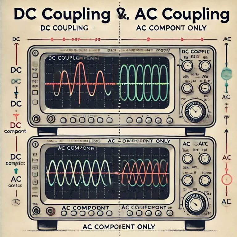
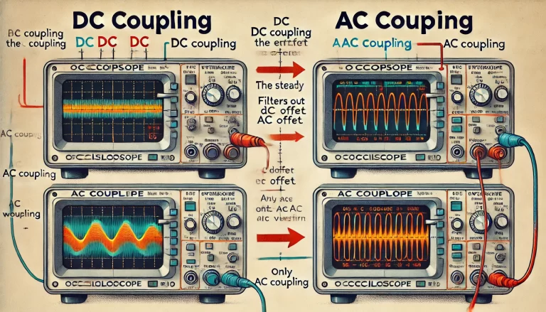
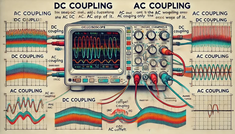
DC coupling allows the oscilloscope to display both the direct current (DC) component and the alternating current (AC) component of a signal. In this mode, no part of the signal is filtered out. Whether the signal includes a steady voltage (DC) or a fluctuating one (AC), both will be visible on the screen.

How It Works:
- DC coupling passes the entire input signal directly to the oscilloscope, showing any constant offset along with the variations.
- For example, if you are measuring a signal that has a 2V DC offset with a superimposed AC waveform, the oscilloscope will show the AC signal riding on top of this 2V offset.
- This is important when measuring signals that contain both a static (DC) part and a dynamic (AC) part, such as power supplies or sensor outputs.
Use Cases for DC Coupling:
- Power Supplies: When analyzing power rails, it’s crucial to know both the steady voltage (DC) and any superimposed noise or ripple (AC).
- Sensor Outputs: Many sensors output signals with a steady DC bias along with superimposed small-signal variations, which makes DC coupling useful for seeing the full signal.
Example:
Imagine you’re measuring the voltage from a temperature sensor. The sensor provides a baseline voltage (DC component) that represents the current temperature and fluctuates slightly (AC component) due to environmental changes. DC coupling allows you to see both components simultaneously.
What is AC Coupling?
AC coupling, on the other hand, blocks the DC component and allows only the AC component of the signal to pass through to the oscilloscope. This is done by placing a capacitor in the signal path, which effectively filters out any steady voltage (DC) and allows only changing signals (AC) to be displayed.

How It Works:
- AC coupling uses a high-pass filter (often a capacitor) to remove any constant voltage (DC offset) from the signal.
- This makes it ideal for situations where the DC offset is not important, and the focus is on viewing the time-varying parts of the signal.
- After applying AC coupling, the signal will appear centered on the oscilloscope’s horizontal axis, as any constant offset is removed.
Use Cases for AC Coupling:
- Audio Signals: When analyzing audio signals, you’re typically not interested in any constant DC offset. AC coupling allows you to focus on the waveform’s fluctuations, such as the actual sound wave.
- Communication Signals: When looking at high-frequency data, such as a modulated signal, AC coupling can help you isolate the relevant signal without distractions from any DC bias.
- Small AC signals riding on large DC offsets: When the AC component is much smaller compared to the DC offset, AC coupling allows you to zoom in on the variations without the larger DC part dominating the display.
Example:
Suppose you are troubleshooting a microphone circuit. The signal from the microphone might have a small AC signal (representing the sound) riding on top of a large DC bias. If you only care about the sound wave, using AC coupling will block the DC part and let you see the sound wave clearly.
DC Coupling vs. AC Coupling: A Side-by-Side Comparison
| Feature | DC Coupling | AC Coupling |
|---|---|---|
| Displays | Both DC (steady) and AC (fluctuating) | Only AC (fluctuating) |
| DC Offset | Visible | Filtered out |
| Use Case | Power supplies, sensors, mixed signals | Audio signals, communication, AC signals |
| Signal Focus | Full signal (steady + varying components) | Varying components (ignores steady part) |
| High-Pass Filter | No | Yes (filters out steady DC part) |
When to Use DC or AC Coupling?
Use DC Coupling when:
- You need to see the entire signal, including any constant (DC) offset.
- You’re analyzing signals that contain important DC information, such as the output of a power supply.
- You’re interested in both the steady voltage level and any fluctuations (such as noise).
Use AC Coupling when:
- You want to focus on the time-varying (AC) part of the signal, and the DC part is irrelevant or distracting.
- The DC offset is large compared to the AC signal, and you want to remove the offset to better see the fluctuations.
- You are analyzing audio signals, communication signals, or other waveforms where the AC component is the key interest.

Conclusion
Understanding when to use DC coupling versus AC coupling on an oscilloscope is crucial for accurate signal analysis. DC coupling provides a complete view of the signal, including both steady and varying components, while AC coupling helps isolate the fluctuating part by filtering out any constant voltage. Depending on the signal you’re analyzing, selecting the appropriate coupling mode will make it easier to diagnose issues and understand the characteristics of the waveform.
By mastering this feature, you can enhance your signal measurement precision, making it easier to focus on the most relevant parts of a signal in various applications.
