Safety Instrumented Systems (SIS) play a critical role in industrial processes, particularly in environments where hazardous events pose significant risks to people, equipment, and the environment. A well-designed SIS is crucial for maintaining safe operations, and its reliability is often defined by its safety integrity. Safety integrity measures the ability of a SIS to perform its intended function when required, under all specified conditions. Understanding the components and factors that contribute to the safety integrity of a SIS is essential for ensuring optimal system performance and risk mitigation.

Key Components of Safety Integrity in SIS
Safety Integrity Level (SIL)
One of the foundational aspects of safety integrity is the Safety Integrity Level (SIL). SIL is a measure of risk reduction provided by a SIS, expressed through a grading system ranging from SIL 1 (lowest) to SIL 4 (highest). Each SIL level corresponds to a specific range of risk reduction factors and failure probabilities, defined by international standards such as IEC 61508 and IEC 61511.
- SIL 1 provides the least risk reduction and is typically applied in systems with relatively low hazard levels.
- SIL 2 and SIL 3 are more common in industries such as oil and gas, chemicals, and pharmaceuticals, where safety is paramount.
- SIL 4 is rare, reserved for highly hazardous processes where the potential consequences of failure are catastrophic.
Determining the appropriate SIL for a system is based on a risk assessment, where potential hazards are identified, and the required risk reduction is calculated. The higher the SIL, the greater the level of reliability and risk mitigation required, and correspondingly, the more stringent the design, implementation, and testing requirements.
2. Fail-safe Design
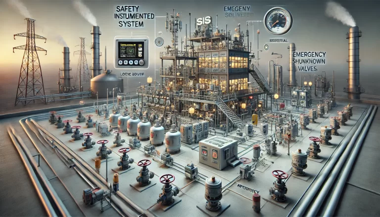
Fail-safe design ensures that, in the event of a failure, the system defaults to a safe state. This is achieved through redundancy, diversity, and failover mechanisms. Key principles of fail-safe design include:
Redundancy: Incorporating multiple layers of backup components, such as sensors, logic solvers, and actuators, ensures that a failure in one component does not result in the failure of the entire system. For example, using dual or triple redundancy (1oo2 or 2oo3 voting logic) means that the system can still operate safely even if one element fails.
Diversity: Using different types of technologies or components to perform the same function helps to mitigate common-cause failures. For example, using both mechanical and electronic sensors to monitor the same parameter reduces the likelihood of simultaneous failure.
Degraded Mode Operation: In some cases, systems are designed to continue operation in a reduced capacity (degraded mode) if a failure occurs, allowing operators time to address the issue without compromising safety.
3. Functional Safety Verification
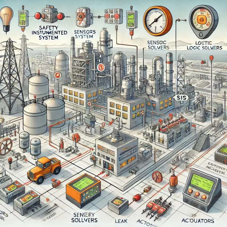
Once the SIS has been designed, it must be rigorously tested and verified to ensure it meets the safety requirements specified during the design phase. This process is known as functional safety verification and includes:
- Factory Acceptance Testing (FAT): Conducted at the manufacturer’s site to ensure all system components are functioning as intended before installation.
- Site Acceptance Testing (SAT): Performed after installation at the site to confirm that the system operates correctly within the operational environment.
- Operational Tests: Ongoing tests to ensure the system continues to function as required during operation, including regular testing of sensors, logic solvers, and actuators.
Verification ensures that the system complies with the functional safety standards and that any deviations are identified and corrected before the system goes into full operation.
4. Failure Mode and Effects Analysis (FMEA)
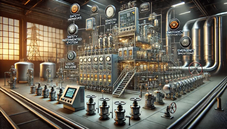
A critical step in evaluating the safety integrity of a SIS is conducting a Failure Mode and Effects Analysis (FMEA). This analysis helps to identify potential failure modes within the system, their causes, and the possible effects on system performance. By understanding these potential failures, the design can be adjusted to either prevent them or mitigate their impact.
FMEA is a proactive approach to ensuring that safety risks are minimized by addressing weaknesses in the system before they lead to unsafe conditions. It includes:
- Identification of Failure Modes: Recognizing ways in which individual components might fail (e.g., sensor malfunction, power supply interruption).
- Evaluation of Effects: Determining how each failure mode could impact overall system performance and safety.
- Mitigation Measures: Implementing design improvements, such as adding redundancy or improving diagnostics, to reduce the likelihood of failure or minimize its impact.
5. Lifecycle Management
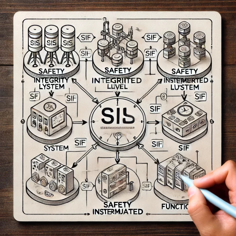
The safety integrity of a SIS is not only dependent on its initial design and implementation but also on its continued maintenance and monitoring throughout its operational life. Lifecycle management refers to the ongoing activities required to ensure that the SIS continues to provide the required level of risk reduction.
Key activities in lifecycle management include:
- Routine Testing: Periodic testing of the system, including all sensors, logic solvers, and final elements, to ensure that all components are functioning correctly.
- Maintenance and Calibration: Regular maintenance and recalibration of system components to prevent drift or degradation in performance over time.
- Modification Management: Any modifications to the system, whether due to operational changes or technology upgrades, must be evaluated to ensure they do not compromise the safety integrity. Changes must be carefully controlled and documented to maintain compliance with safety standards.
- Decommissioning: At the end of its useful life, the SIS must be safely decommissioned, with consideration given to preventing residual risks during this phase.
6. Diagnostics and Recovery
Diagnostics play a crucial role in maintaining the safety integrity of a SIS by allowing for the early detection of failures or performance degradation. Advanced diagnostic tools continuously monitor system health and alert operators when a potential issue is identified. This allows for proactive maintenance and minimizes the risk of system failure during operation.
Additionally, recovery mechanisms ensure that, once a failure is detected, the system can either automatically revert to a safe state or initiate recovery protocols. Manual interventions by operators may also be necessary in certain situations, making the availability of real-time data and decision-making tools essential for safe operations.
7. Adaptability to Environmental and Operational Conditions
The SIS must be designed to withstand the environmental and operational conditions in which it will function. Factors such as temperature extremes, humidity, vibration, dust, and corrosive environments can significantly impact the performance and reliability of system components. It is important to choose materials and designs that can tolerate these conditions and ensure that they are rigorously tested during both the design and operational phases.
In hazardous locations, SIS components must meet the necessary certification requirements (e.g., ATEX, IECEx) for operation in explosive atmospheres, ensuring that safety integrity is maintained even in the most challenging environments.
Conclusion
The safety integrity of a Safety Instrumented System (SIS) is critical to ensuring the safe operation of industrial processes. Achieving high safety integrity requires careful consideration of factors such as the appropriate Safety Integrity Level (SIL), robust fail-safe design, thorough functional safety verification, and continuous lifecycle management. By integrating these elements, SIS can effectively reduce risks and protect people, assets, and the environment from hazardous events. Ongoing diagnostics, regular maintenance, and the ability to adapt to operational and environmental conditions are essential for maintaining the safety integrity of a SIS over time.
